Subtitle detection apparatus, subtitle detection method and pull-down signal detection apparatus
- Summary
- Abstract
- Description
- Claims
- Application Information
AI Technical Summary
Benefits of technology
Problems solved by technology
Method used
Image
Examples
first embodiment
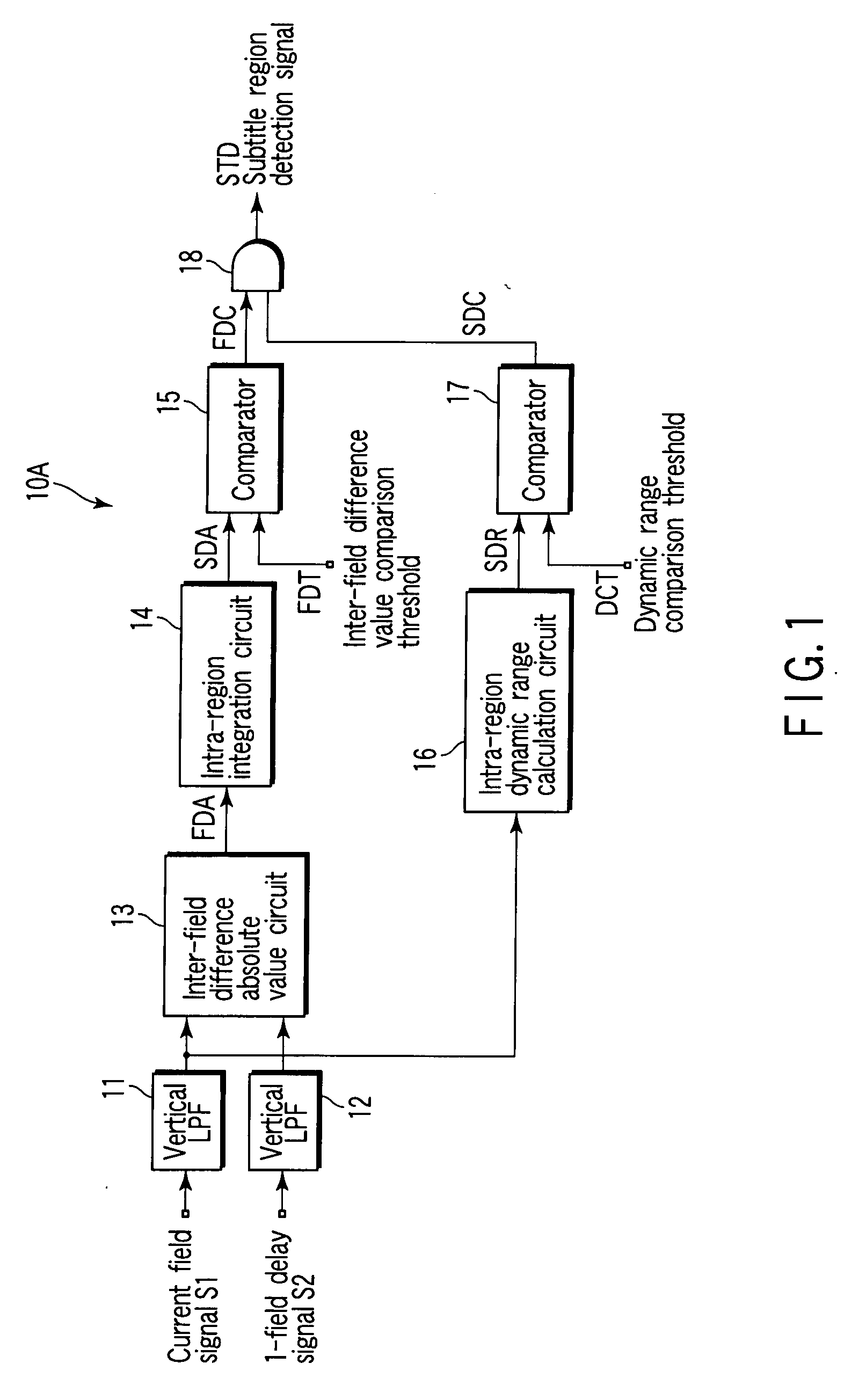
[0030]FIG. 1 is a block diagram that shows the structure of a subtitle detection apparatus 10A according to the present invention.
[0031]A current field signal (luminance signal) S1 passes through a first vertical low-pass filter (LPF) 11, and is then input to an inter-field difference absolute value circuit 13 and to an intra-region dynamic range calculation circuit 16. A 1-field delay signal S2 passes through a second vertical LPF 12, and is then input to the inter-field difference absolute value circuit 13. The 1-field delay signal S2 is a signal which is obtained by delaying the current field signal S1 by a 1-field period by using a memory circuit, as will be described later in detail with reference to FIG. 8. The first and second vertical LPFs 11 and 12 remove vertical high-frequency noise in 1 field, and align vertical median points of the current field signal S1 and 1-field delay signal S2. A horizontal LPF may be used for the noise removing filter.
[0032]The inter-field differ...
second embodiment
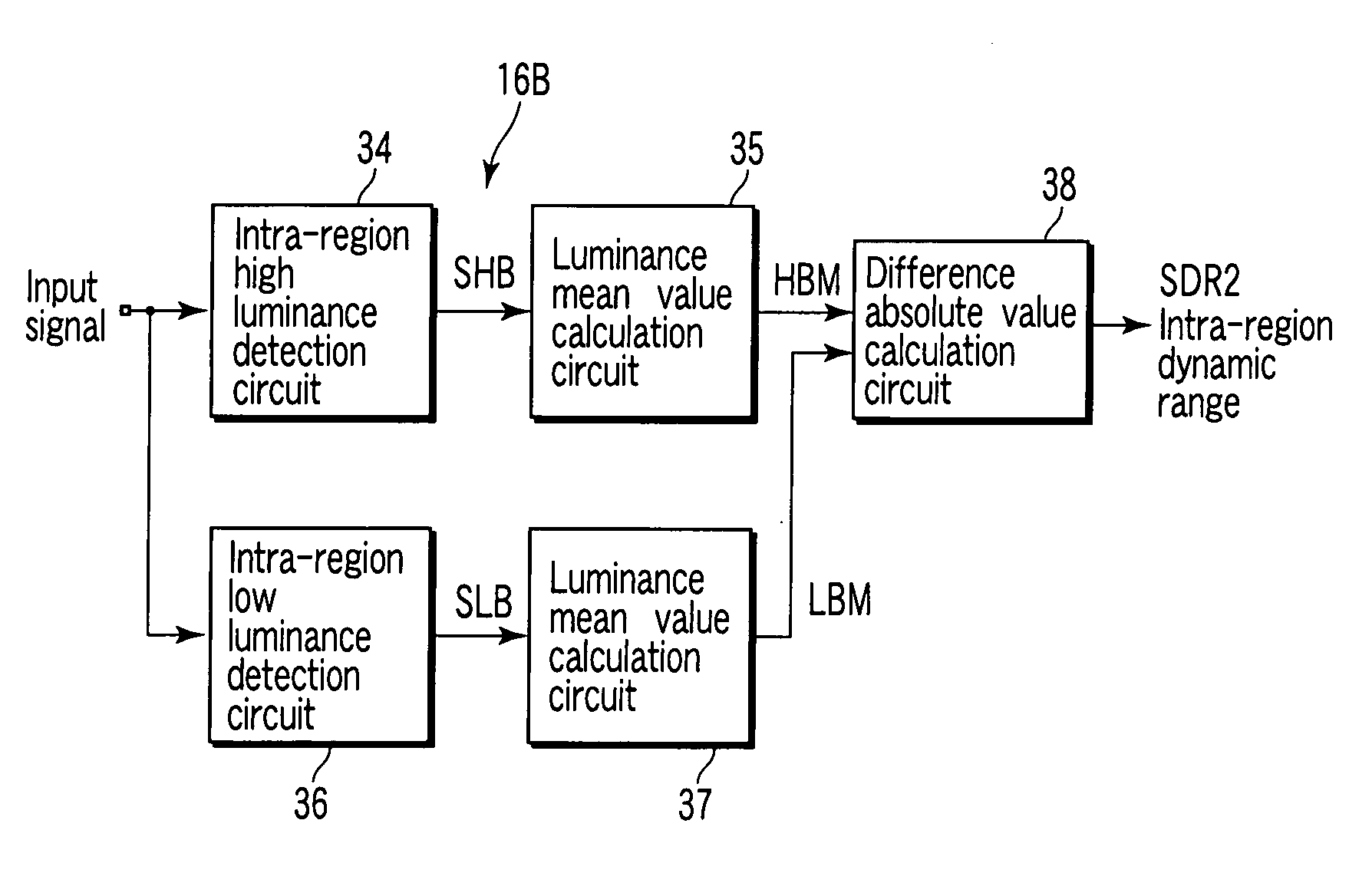
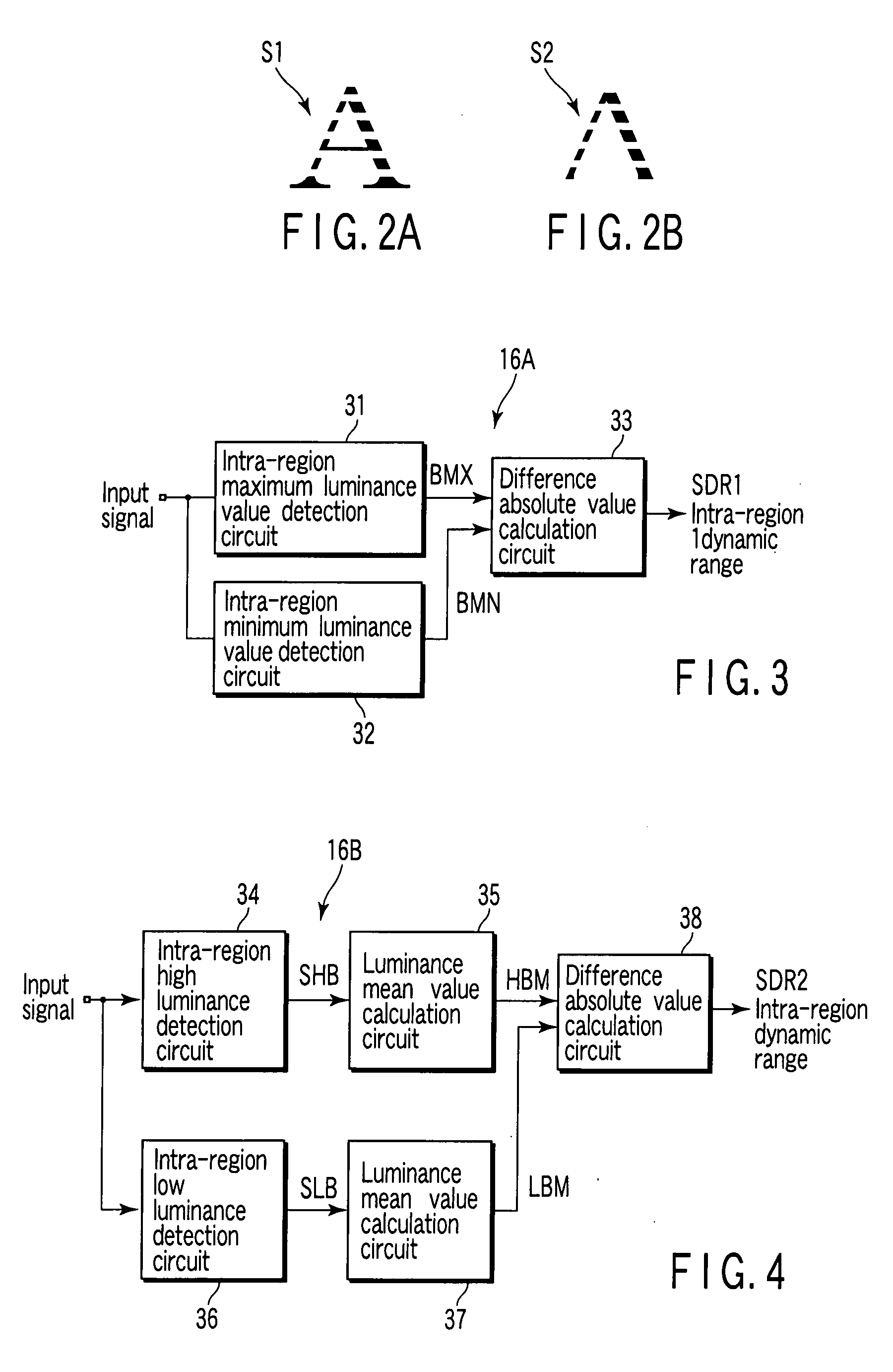
[0040]FIG. 4 shows a dynamic range calculation circuit 16B as the dynamic range calculation circuit 16.
[0041]An intra-region high luminance detection circuit 34 receives the current field signal S1 from the vertical LPF 11, extracts first to n-th high luminance values in the region, and outputs the extracted values as high luminance SHB. A high luminance mean value calculation circuit 35 calculates a mean value HBM of the high. luminance SHB. For example, if n is 4, a highest luminance in the region is 100, a second highest luminance in the region is 99, the number of pixels with luminance 100 is 1 and the number of pixels with luminance 99 is 4, the high luminance mean value calculation circuit 35 calculates (100+99*3) / 4 as a high luminance mean value HBM, and outputs 99.25 as the high luminance mean value HBM.
[0042]An intra-region low luminance detection circuit 36 receives the current field signal S1 from the vertical LPF 11, extracts first to n-th low luminance values in the reg...
third embodiment
[0049]FIG. 6 is a block diagram that shows the structure of a subtitle detection apparatus 10C according to the present invention. The subtitle detection apparatus 10C includes a comparator 21 and an intra-region high-luminance-pixel-number counting circuit 22, which are substituted for the dynamic range calculation circuit 16 of the subtitle detection apparatus 10A shown in FIG. 1.
[0050]As described above, in general, a character in a subtitle region is displayed in white with maximum luminance. By the comparator 21, intra-region high-luminance-pixel-number counting circuit 22 and comparator 23, the number of pixels with high luminance in the region is counted and if the number of high-luminance pixels is greater than a comparison threshold value HBT, the region is determined to be a subtitle region.
[0051]The comparator 21 compares the current field signal S1 from the vertical LPF 11 with a luminance level comparison threshold value BLT. If the value of the current field signal S1 ...
PUM
 Abstract
Description
Claims
Application Information
 - R&D
- Intellectual Property
- Life Sciences
- Materials
- Tech Scout
- Unparalleled Data Quality
- Higher Quality Content
- 60% Fewer Hallucinations
Browse by: Latest US Patents, China's latest patents, Technical Efficacy Thesaurus, Application Domain, Technology Topic, Popular Technical Reports.
© 2025 PatSnap. All rights reserved.Legal|Privacy policy|Modern Slavery Act Transparency Statement|Sitemap|About US| Contact US: help@patsnap.com


