
Supporting plate, stage device, exposure apparatus, and exposure method

a stage device and support plate technology, applied in the field of supporting plates, can solve problems such as device/member failure, rust/oxidation, and liquid on the wafer may increase and be splashed at the periphery, and achieve the effect of reducing the effects of problems and suppressing problems

Inactive Publication Date: 2007-09-27
NIKON CORP
View PDF28 Cites 0 Cited by
  • Summary
  • Abstract
  • Description
  • Claims
  • Application Information

AI Technical Summary

Benefits of technology

The invention provides a supporting plate that prevents liquid from splashing and leaking, and a stage device and exposure apparatus that use this supporting plate to prevent device / member failure, leaking, rust / oxidation, and other problems caused by liquid immersion. The supporting plate is made to be liquid repellent and has a collection device to collect any splashed or discharged liquid. The stage device and exposure method use the supporting plate to hold a substrate and expose a pattern onto the substrate via liquid filled between the projection optical system and the substrate. The invention also provides a method for collecting the liquid and a method for exposing a pattern on a substrate.

Problems solved by technology

The following problems exist in the above-mentioned apparatus that utilizes liquid immersion.
In the above-mentioned exposure apparatus, exposure is performed in a state in which liquid is filled between a projection optical system and a wafer, so there are cases in which liquid may be splashed to locations external of the wafer if an unexpected operation is performed due to errors when a stage moves.
However, once the operation of the liquid collection mechanism stops in a state in which the liquid supply mechanism is still operated, there is a possibility that the liquid on the wafer may increase and be splashed at the periphery.
Because of this, in a liquid immersion exposure apparatus, there is a possibility that problems may occur such as device / member failure, leaking, rust / oxidation, etc. due to splashed liquid.
Furthermore, in this case, there also is a problem that exposure processing cannot be performed well.

Method used


Image

  • Supporting plate, stage device, exposure apparatus, and exposure method
  • Supporting plate, stage device, exposure apparatus, and exposure method
  • Supporting plate, stage device, exposure apparatus, and exposure method

Examples


first embodiment

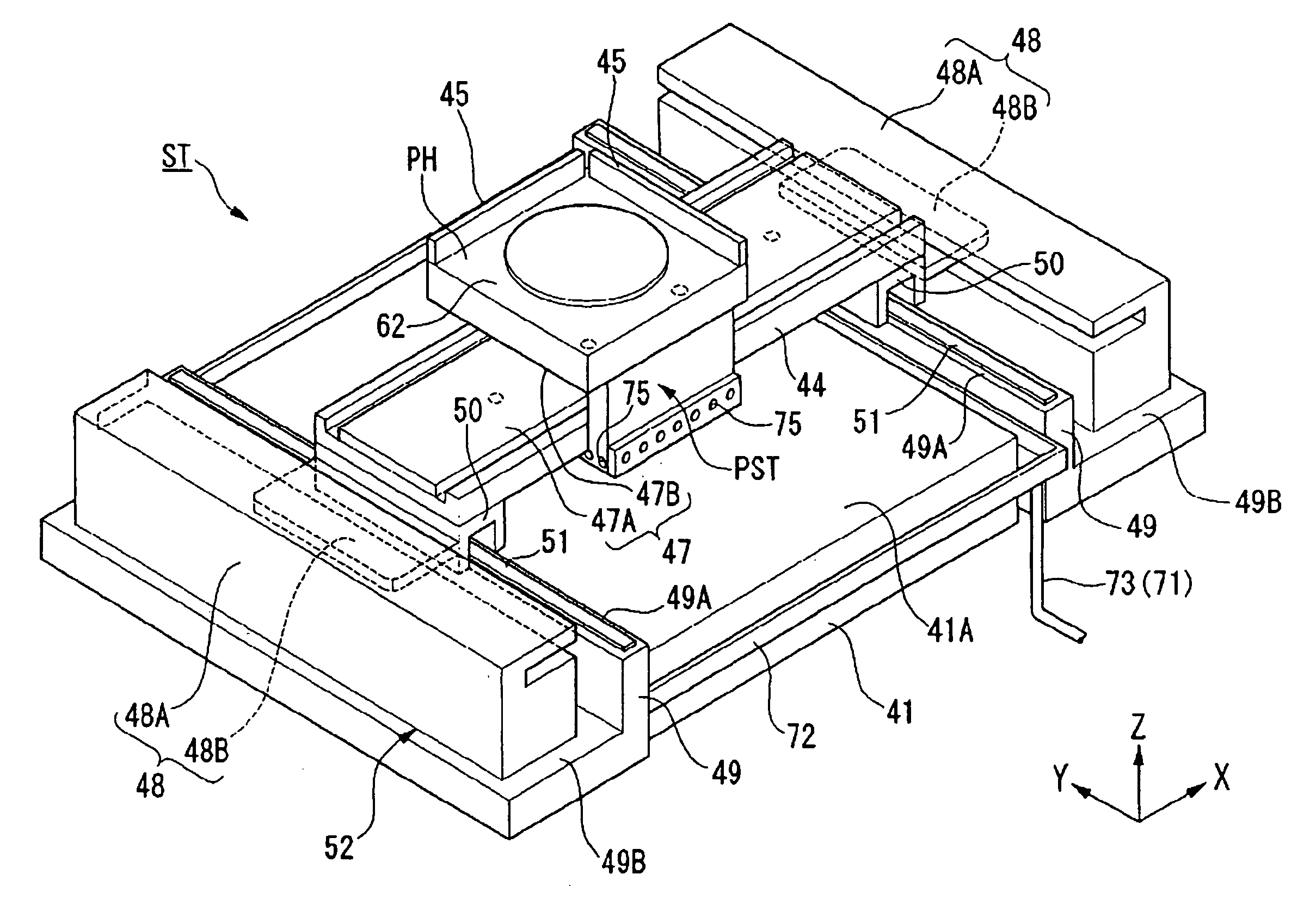
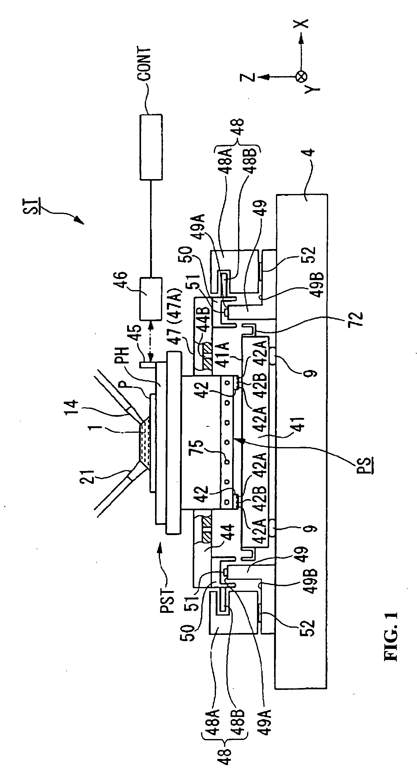
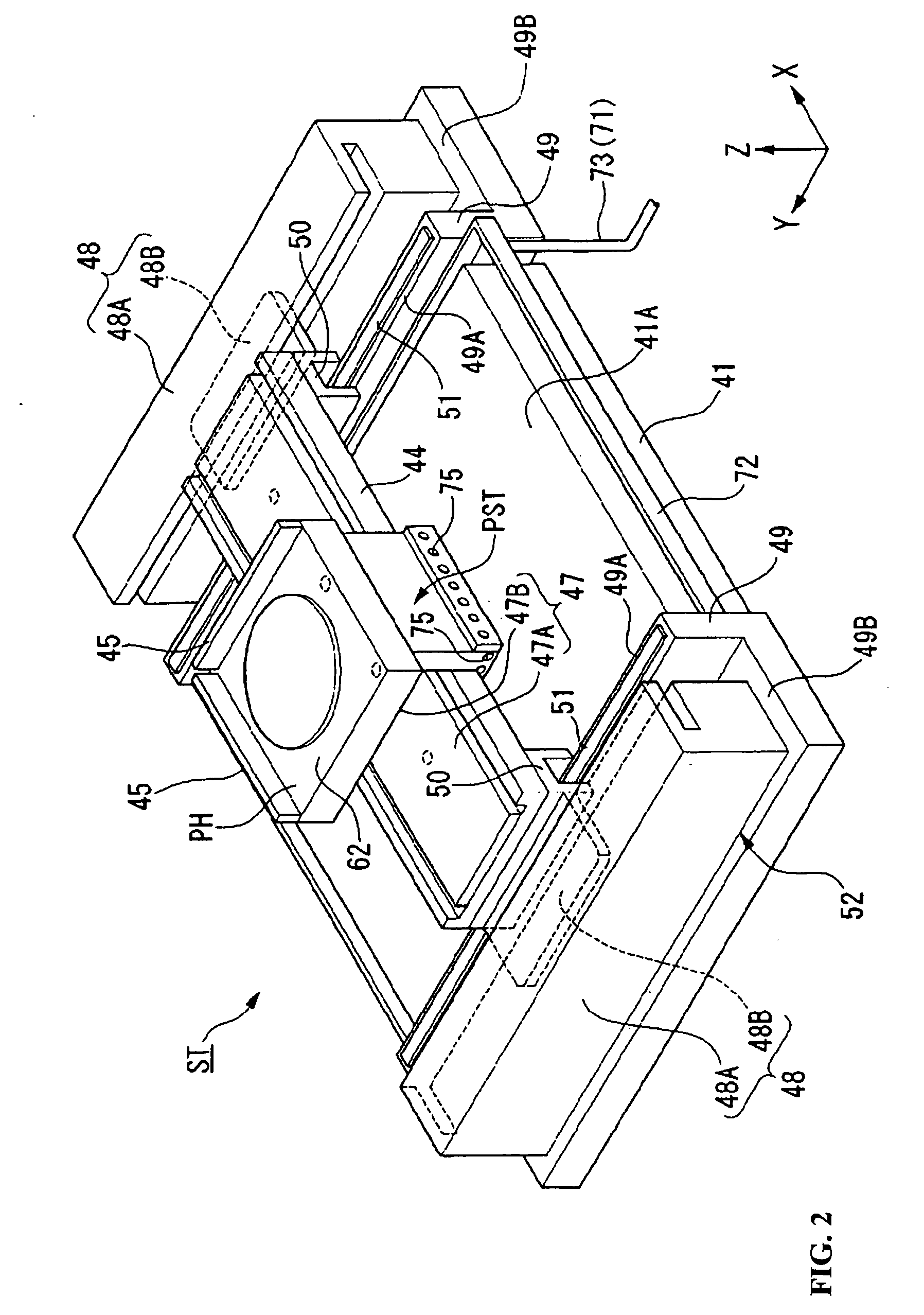
[0036] A first embodiment explains a supporting plate according to some aspects of this invention, and a stage device provided with this supporting plate. FIG. 1 is a schematic structural diagram showing an embodiment of a stage device utilizing some aspects of this invention.

[0037] A stage device ST shown in FIG. 1 is mainly constituted by a substrate supporting plate (supporting plate) 41 which is supported by three or four points on a base plate 4 via a vibration isolation unit (removal device) 9, a substrate stage PST as an object (movable body) which supports the substrate P and moves a top surface (support surface) 41A of the substrate supporting plate 41, an X linear motor 47 which drives the substrate stage PST in an X axis direction (horizontal direction in FIG. 1), and a Y linear motor 48 which drives the substrate stage PST in a Y axis direction (direction perpendicular to a paper plane of FIG. 1). The vibration isolation unit 9 is provided with an actuator such as an air...

second embodiment

[0061] Next, a supporting plate and stage device utilizing aspects of this invention is explained. FIG. 4 is a diagram schematically showing the substrate stage PST, the substrate supporting plate 41, and the X guide stage 44 within the stage device. Furthermore, in FIG. 4, the moving mirror and the substrate on the substrate stage PST, and the gutter of the substrate supporting plate 41 are omitted from the drawing, although they would be present in the actual device.

[0062] In this embodiment, as shown in FIG. 4, on the top surface of the table portion PH of the substrate stage PST, a groove portion 76 is formed along an edge (outer circumference). Furthermore, on one side surface of the table portion PH, a slot portion 77 is formed which is positioned above a concave portion 44C of the X guide stage44, and extends in the Z axis direction, and is connected to the groove portion 76.

[0063] Furthermore, in the concave portion 44C of the X guide stage 44, a drain port 44B is formed at...


PUM

PropertyMeasurementUnit
exposure wavelengthaaaaaaaaaa
wavelengthaaaaaaaaaa

Abstract

An exposure apparatus exposes a pattern onto a substrate. The exposure apparatus includes a supporting plate having a surface, a substrate stage which holds the substrate and is movable over the supporting plate, a liquid supply device having a supply nozzle which supplies liquid to the substrate, a first collection device which collects the liquid directly from the substrate, and a second collection device which collects liquid which has been discharged to the supporting plate.

Description

[0001] This is a Division of U.S. patent application Ser. No. 10 / 972,366 filed Oct. 26, 2004. The disclosure of the prior application is hereby incorporated by reference herein in its entirety.[0002] The disclosure of each of the following priority applications is herein incorporated by reference in its entirety: Japanese Patent Application No. 2003-373084 filed Oct. 31, 2003 and Japanese Patent Application No. 2004-309324 filed Oct. 25, 2004. BACKGROUND OF THE INVENTION [0003] 1. Field of the Invention [0004] This invention relates to a supporting plate, a stage device, an exposure device, and an exposure method, and particularly to a supporting plate which is advantageously used with respect to a substrate on a stage, a stage device, an exposure apparatus, and an exposure method, at the time of exposure via a projection optical system that utilizes a liquid immersion technique. [0005] 2. Description of Related Art [0006] A semiconductor device and a liquid crystal display device a...

Claims


Application Information

Patent Timeline
Patent Type & Authority Applications(United States)
IPC IPC(8): G03B27/58G03F7/20H01L21/027
CPCG03F7/70341G03F7/7095G03F7/70716G03F7/707
Inventor ARAI, DAI
Owner NIKON CORP
Learn More