Stabilized Solid-State Laser Gyro and Anisotropic Lasing Medium

Inactive Publication Date: 2007-09-27
THALES SA
View PDF11 Cites 14 Cited by
  • Summary
  • Abstract
  • Description
  • Claims
  • Application Information

AI Technical Summary

Benefits of technology

[0012] The object of the invention is to propose a feedback device for a solid-state laser gyro comprising an intracavity optical assembly, making it possible to regulate the intensity of the counterpropagating optical modes, based no longer on optical losses dependent on the direction of propagation but based on an optical gain that depends on the propagation direction of the optical mode on its intensity. The feedback device therefore modulates the optical gain according to the difference in intensity between the two transmitted modes in order to favor the weaker mode to the detriment of the other, so as constantly to slave the intensity of the two counterpropagating modes to a common value or to a constant difference.

Problems solved by technology

This is not a priori an easy thing to achieve because of the intermodal competition phenomenon, which means that one of the two counterpropagating modes may have a tendency to monopolize the available gain, to the detriment of the other mode.
However, the gaseous nature of the amplifying medium is a source of technical complications when producing the laser gyro especially because of the high gas purity required and of premature wear during its use, which wear is in particular due to gas leakage and to deterioration of the electrodes by the high voltages used to establish the population inversion.
However, such a construction is made very difficult to achieve due to the homogeneous character of the broadening of the gain curve of the solid-state media, which induces very strong intermodal competition and because of the existence of a large number of different operating regimes, among which the non-frequency-locked intensity-balanced bidirectional regime, called the “beat regime” is one very unstable particular case (N. Kravtsov and E. Lariotsev, Self-modulation oscillations and relaxations processes in solid-state ring lasers, Quantum Electronics 24 (10), 841-856 (1994)).
This major physical obstacle has greatly limited hitherto the development of solid-state laser gyros.

Method used


Image

  • Stabilized Solid-State Laser Gyro and Anisotropic Lasing Medium
  • Stabilized Solid-State Laser Gyro and Anisotropic Lasing Medium
  • Stabilized Solid-State Laser Gyro and Anisotropic Lasing Medium

Examples


first embodiment

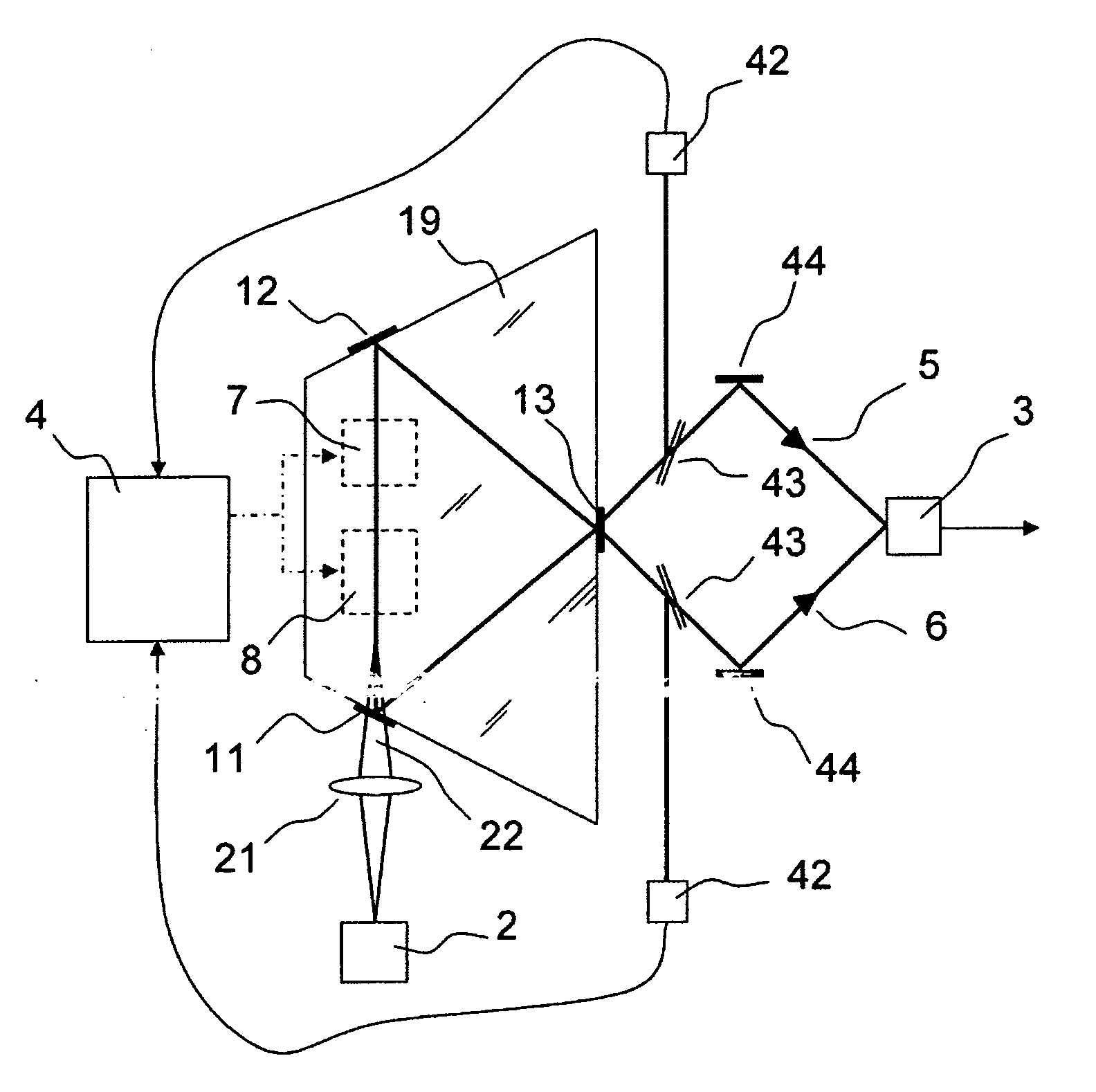
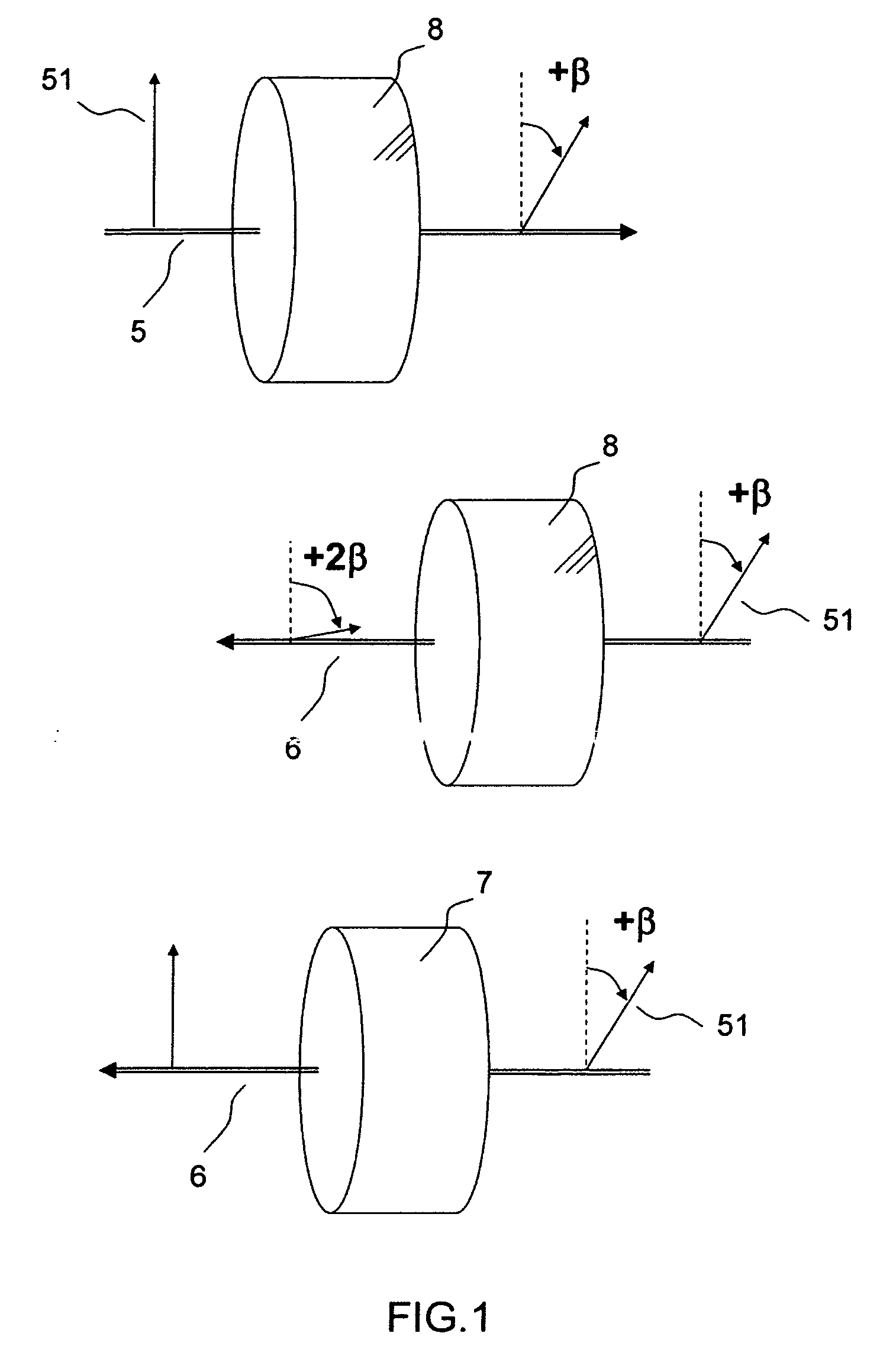
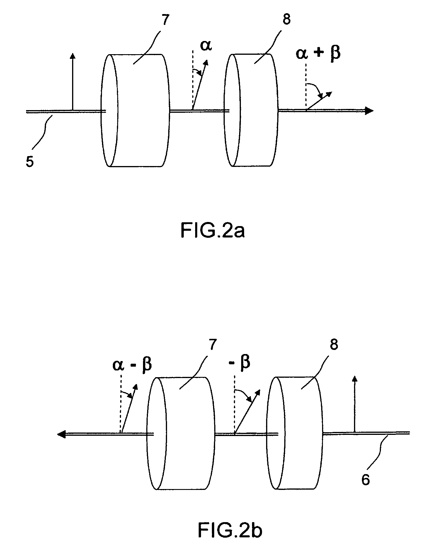
[0031]FIG. 3 describes the general principle of the laser gyro in the first embodiment according to the invention. It includes a laser cavity having 3 mirrors 11, 12 and 13, said cavity comprising a reciprocal rotator or a waveplate 7, a nonreciprocal rotor 8, these elements being similar to those of FIGS. 2a and 2b, and an anisotropic lasing medium 19. For example, the first element 7 exhibiting a reciprocal effect-rotates the polarization of the light through an angle α in the forward direction and the second element 8 rotates the polarization through an angle β, again in the forward direction. An optical mode linearly polarized in the same polarization direction as that of the stimulated emission in the lasing medium is amplified with a maximum gain and can thus oscillate efficiently. When such an intra-cavity mode makes a complete revolution of the cavity, undergoing firstly the reciprocal effect and then the nonreciprocal effect, its plane of polarization rotates through an ang...

second embodiment

[0038] In the invention, in particular, it is possible to use a nonplanar cavity as described in FIGS. 4a and 4b instead of an optical element acting on the polarization state of the counterpropagating modes. Consider a cavity 1 having at least four mirrors 11, 12, 13 and 14. It is possible to place them, as indicated in FIG. 4a, in such a way that the counterpropagating beams propagate in one plane (the (X, Y) plane in FIG. 4a). In this case, if these beams are linearly polarized, the polarization direction is maintained. It is also possible to place them in such a way that the counterpropagating beams no longer propagate in one plane, as indicated for example in FIG. 4b, in which the mirror 12 has been displaced along the Z axis. In this case, it has been demonstrated that the polarization direction of the counterpropagating beams has rotated through an angle that depends on the geometry of the cavity when the beam has made one complete revolution in the cavity (A. C. Nilsson, E. ...


PUM


Abstract

The field of the invention is that of solid-state laser gyros. One of the major inherent problems in this technology is that the optical emission of this type of laser is by nature highly unstable in terms of power. To reduce this instability, the invention proposes to introduce, into the cavity, optical gains controlled by the installation of an optical assembly comprising an anisotropic lasing medium, a first optical element and a second optical element exhibiting a nonreciprocal effect, each acting on the polarization of the counterpropagating optical modes, at least one of these two effects being variable, thus making it possible to introduce controlled optical gains that depend on the propagation direction of the counterpropagating optical modes. Several devices are described and employ either fixed effects of the element that are combined with variable nonreciprocal effects, or the reverse. These devices apply in particular to monolithic-cavity lasers.

Description

CROSS REFERENCE TO RELATED APPLICATIONS [0001] The present Application is based on International Application No. PCT / EP2004 / 053062, filed on Nov. 23, 2004, which in turn corresponds to FR 03 / 14598 filed on Dec. 12, 2003, and priority is hereby claimed under 35 USC §119 based on these applications. Each of these applications are hereby incorporated by reference in their entirety into the present application.BACKGROUND OF THE INVENTION [0002] 1. Field of the Invention [0003] The field of the invention is that of solid-state laser gyros used as inertial control unit. This type of equipment is used especially for aeronautical applications. [0004] The laser gyro, developed some thirty years ago, is widely used on a commercial scale at the present time. Its principle of operation is based on the Sagnac effect, which induces a frequency difference Δν between the two optical transmission modes that propagate in opposite directions, called counterpropagating modes, of a bidirectional laser r...

Claims


Application Information

Patent Timeline
IPC IPC(8): G01C19/66H01S3/083
CPCH01S3/083G01C19/66
Inventor FEUGNET, GILLESPOCHOLLE, JEAN-PAULSCHWARTZ, SYLVAIN
Owner THALES SA
Why Eureka
Try Eureka