Exhaust gas purifying system

a technology of exhaust gas and purification system, which is applied in the direction of mechanical equipment, machines/engines, separation processes, etc., can solve the problems of increasing pressure loss, decreasing purification efficiency of honeycomb catalytic members, and increasing pressure loss, so as to achieve excellent purification efficiency and reduce pressure loss , the effect of mounting in limited spa

Active Publication Date: 2007-09-27
NGK INSULATORS LTD
View PDF3 Cites 32 Cited by
  • Summary
  • Abstract
  • Description
  • Claims
  • Application Information

AI Technical Summary

Benefits of technology

[0014]The exhaust gas purifying system of the present invention presents advantages of excellent purifying efficiency of

Problems solved by technology

However, pressure loss also tends to increase in inverse proportion to square of hydraulic diameter of cell.
Therefore, improvement in transmissibility of components to be purified is accompanied with the problem of increased pressure loss.
When the components to be purified diffuse in the catalytic l

Method used


Image

  • Exhaust gas purifying system
  • Exhaust gas purifying system
  • Exhaust gas purifying system

Examples


example 1

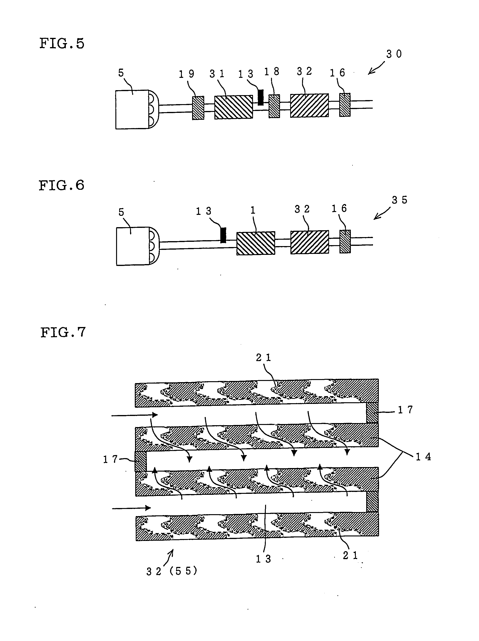
[0067]A honeycomb catalyst carrier made of cordierite whose end is alternately plugged was prepared. This honeycomb catalyst carrier had outer diameter: 144 mm, length: 152 mm, cell density: 46. 5 cells / cm2, partition wall thickness: 0.305 mm, mean pore size of partition wall: 25 μm, and porosity: 65%. By carrying copper-substituted zeolite on porous surface and partition wall surface of the honeycomb catalyst carrier in an amount of 200 g / L per volume of the honeycomb catalyst carrier, NOx purifying catalytic member (1) was prepared (structure: see FIG. 10).

[0068]A honeycomb structure member made of cordierite whose end is alternately plugged was prepared. This honeycomb structure member had outer diameter: 144 mm, length: 152 mm, cell density: 46.5 cells / cm2, partition wall thickness: 0.305 mm, mean pore size of partition wall: 15 μm, and porosity: 60%. By coating porous surface and partition wall surface of the honeycomb structure member with oxidation catalyst carrying Pt on gri...

examples 2 to 17

[0073]An exhaust gas purifying system (Examples 2 to 17) was produced in a similar manner to Example 1 described above except that constructions of NOx purifying catalytic member and DPF, and layout of constituents are changed as shown in Table 1. Results of determined NOx purifying efficiency (%), and pressure loss (relative value) are shown in Table 1.

TABLE 1NOx purifyingMean porecatalytic membersize (μm)PartitionNOxDPF mean poreNOxPressureCellwallpurifyingsize / NOx purifyingpurifyinglossdensitythicknessPorosityσ*1catalystcatalytic memberefficiency(relative(cells / cm2)(mm)(%)(μm)StructureDPFmembermean pore size (%)Layout(%)value)Example 146.50.305650.4FIG. 10152560FIG. 485100Comparative46.50.305650.4FIG. 10—25—*220100example 1Example 246.50.305500.4FIG. 10152560FIG. 475105Example 346.50.305450.4FIG. 10152560FIG. 465112Example 446.50.305650.2FIG. 10152560FIG. 480100Example 546.50.305650.4FIG. 10105518.2FIG. 47295Example 646.50.305650.4FIG. 10156224.2FIG. 47095Example 746.50.305650.4F...

examples 18 to 21

[0075]A NOx purifying catalytic member which is identical to that used in Example 1 was prepared. By coating porous surface and partition wall surface of the partition wall of the NOx purifying catalytic member with oxidation catalyst carrying Pt on gamma alumina and ceria in an amount of 100 g / L (Pt: 2 g / L) per volume of honeycomb structure member, a NOx purifying catalytic member (1′) with oxidation catalyst was prepared. DPF (2′) which is identical to Example 1 described above except for coating with oxidation catalyst was prepared.

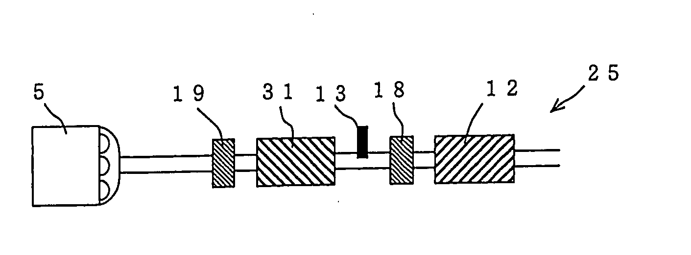
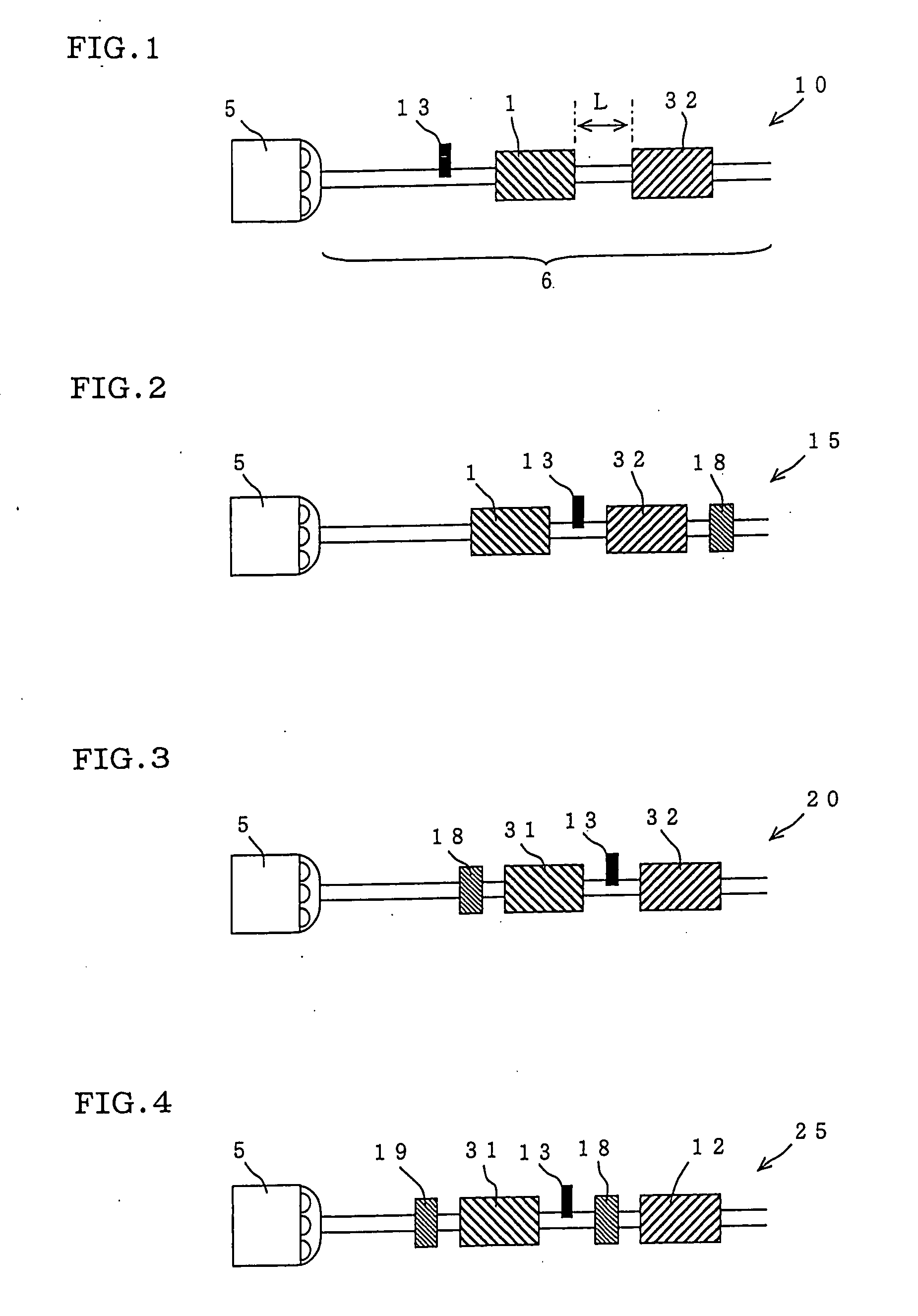
[0076]In an exhaust system of a diesel engine adapted to car of 2 L displacement, the prepared NOx purifying catalytic member (1′), DPF (2′) and oxidation catalytic member (3) were placed in the order of (2′)-(1′)-(3) so that the length between an outlet end face of DPF (2′) and an inlet end face of NOx purifying catalytic member (1′) was 0.1 m, 0.4 m, 0.8 m, and 1.5 m, to create an exhaust gas flow path. Just before the NOx purifying catalytic member ...


PUM

PropertyMeasurementUnit
Lengthaaaaaaaaaa
Fractionaaaaaaaaaa
Fractionaaaaaaaaaa

Abstract

An exhaust gas purifying system has a honeycomb filter including a porous partition wall having a number of pores arranged so that a plurality of cells communicating between two end faces are formed, and a plugging portion disposed in either of the end faces or inside the cell so as to plug the cell; and a NOx purifying catalyst including a honeycomb catalyst carrier having substantially same shape as the honeycomb filter, and a NOx selective reducing SCR catalyst or a NOx occluding catalyst carried on surface of the partition wall and/or on surface of the pores, wherein the honeycomb filter and the NOx purifying catalytic member are disposed in this order in an exhaust gas flow path where exhaust gas discharged from a diesel engine circulates.
To provide an exhaust gas purifying system which realizes excellent purifying efficiency of NOx contained in exhaust gas discharged from a diesel engine, and small pressure loss, and can be mounted in limited space.

Description

TECHNICAL FIELD[0001]The present invention relates to an exhaust gas purifying system suited for use in purification of components to be purified such as nitrogen oxides (NOx) and microparticles (PM) contained in exhaust gas discharged from a diesel engine for automobile.BACKGROUND ART[0002]For cleaning NOx contained in exhaust gas discharged from diesel engines of automobiles and the like, catalytic members having honeycomb structure (honeycomb catalytic members) are currently used. These honeycomb catalytic members have such a structure that a catalytic layer 15 is carried on surface of a partition wall 4 forming a cell 3 as shown in FIG. 8. As shown in FIG. 9, in cleaning exhaust gas using this honeycomb catalytic member 60 (honeycomb structure member 11), exhaust gas is caused to flow into the cell 3 of the honeycomb catalytic member 60 from the side of one end face 2a, and to come into contact with a catalytic layer (not shown) on surface of the partition wall 4, and then to fl...

Claims


Application Information

Patent Timeline
IPC IPC(8): B01D50/00B01D53/34
CPCF01N3/0222F01N13/009F01N3/035F01N3/0821F01N3/0842F01N3/206F01N3/2066F01N2330/06F01N2330/30F01N2330/48F01N2340/02F01N2370/02F01N2510/06F01N2610/02Y02T10/24F01N3/0231Y02T10/12
Inventor MIYAIRI, YUKIOTAKAHASHI, AKIRA
Owner NGK INSULATORS LTD
Why Eureka
Try Eureka