
Controlling an Electronic Device

a technology of electronic devices and control devices, applied in the field of identifying movement, can solve the problems of significant drawbacks that the control does not take into account, substantial compromise the usability of the device, and obvious risk of misrecognition, so as to achieve considerably better identification and fewer erroneous identifications

Inactive Publication Date: 2007-09-27
NOKIA CORP
View PDF4 Cites 24 Cited by
  • Summary
  • Abstract
  • Description
  • Claims
  • Application Information

AI Technical Summary

Benefits of technology

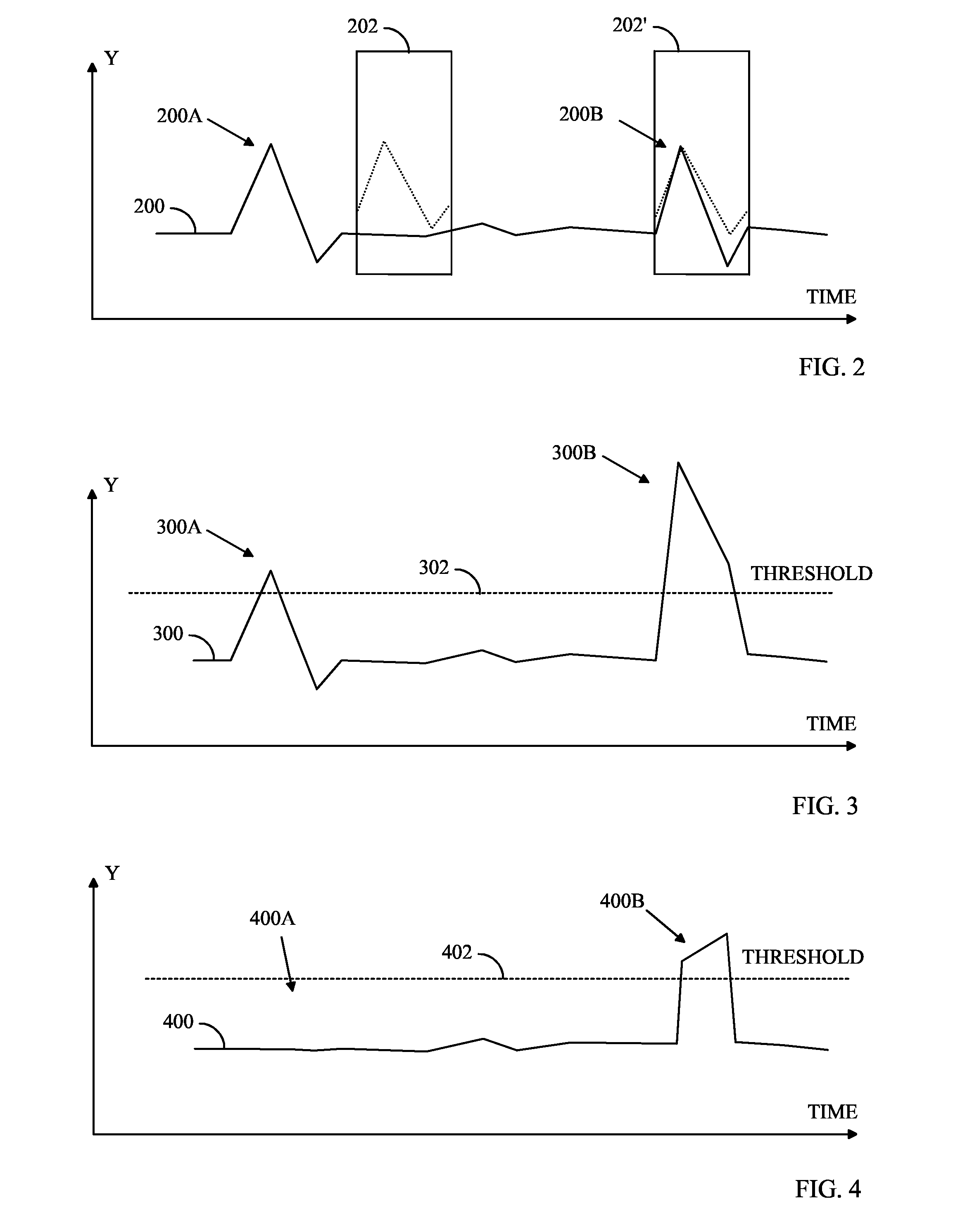
[0004] The object of the invention is thus to provide an improved method and an apparatus for implementing the method in a manner that better takes into consideration the operating situation and / or environment of the device. Accordingly, the object of the invention is a method of controlling an electronic device, comprising identifying a motion pattern in the motion of the device and eliminating the effect of the identified motion pattern from a control motion used for controlling the device.
[0005] The invention also relates to a software product comprising a software routine for receiving measurement information descriptive of a motion of the device, a software routine for identifying a motion pattern in the measurement information, and a software routine for eliminating the effect of the identified motion pattern from a control motion used for controlling the device and included in the measurement information.
[0006] The invention also relates to an electronic device comprising means for identifying a motion pattern in a motion of the device, and means for eliminating the effect of the identified motion pattern from a control motion used for controlling the device.
[0011] An advantage of the method and device of the invention is that the control motions intended to control the device can be identified considerably better and with fewer erroneous identifications once an identified disturbance is eliminated from the control motions.

Problems solved by technology

Said prior art applications are associated with the significant drawback that the control does not take into consideration the environment or the operating situation wherein the device is being used or identification is being performed.
For this reason, should any essential motion-based disturbing factors be associated with the environment or operating situation, the risk of misrecognitions is apparent and substantially compromises the usability of the device.

Method used


Image

  • Controlling an Electronic Device
  • Controlling an Electronic Device
  • Controlling an Electronic Device

Examples


Embodiment Construction

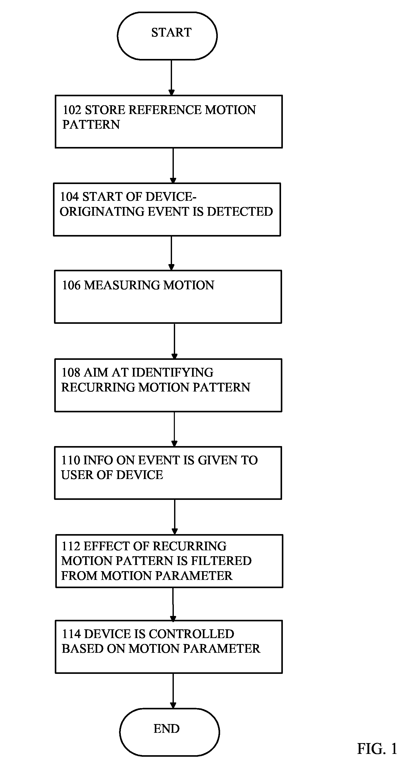
[0018] In the following, an embodiment of the method according to the invention will be described by means of FIG. 1. In the initial step 102 of the method, a given reference motion pattern is stored in an electronic device. The reference motion pattern can be stored in the device for instance at the factory in connection with the manufacture of the device. The stored reference motion patterns may describe the operating environment of the device, for instance that the device is in a train or carried by a person riding a bicycle. The patterns stored in the device as a factory setting may be based for instance on a large number of operating situation examples, from which an average motion pattern is generated. Alternatively, the device may comprise several alternative patterns for a given operating environment, such as a train.

[0019] In addition to the reference motion patterns stored as a factory setting, the user may teach the device the desired patterns. For example, the user may ...


PUM


Abstract

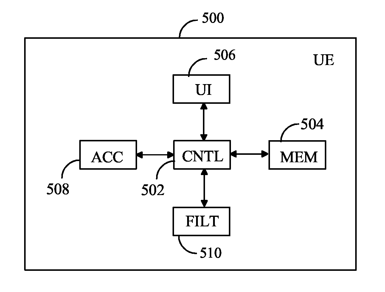
An electronic device (500) comprising means (510) for identifying a motion pattern in a motion of the device, and means (510) for eliminating the effect of the motion pattern from a control motion employed for controlling the device. The identification unit (510) eliminates the effect of an identified motion pattern from the control motion by comparing the motion information measured by the measurement unit (508) with the control motion stored in the memory (504).

Description

BACKGROUND OF THE INVENTION [0001] The invention relates to identifying movement in a mobile environment and particularly to utilizing the identified movement in controlling a device. [0002] Several different manners of controlling an electronic device, such as a mobile telephone, have been developed. Alongside with keyboard-based control, control methods include those wherein the control is based on voice and gestures, for example. In a prior art device, the display can be implemented in such a manner that, irrespective of changes in the orientation of the device, the text of the display can always be read vertically. It is also known to zoom the display by turning the device. Solutions based on acceleration sensors have also been utilized for instance for replacing the keyboard of a computer in such a manner that a given finger position is associated with a given character input. [0003] Said prior art applications are associated with the significant drawback that the control does ...

Claims


Application Information

Patent Timeline
IPC IPC(8): G06F3/00G06FG06F3/01H04M1/72454
CPCG06F3/017H04M2250/12H04M1/72569G06F2200/1636H04M1/72454G06F3/005G06F3/01G06F3/0412G06F3/0484G06F9/04G06F21/316
Inventor RONKAINEN, SAMIMATERO, JUHA P.
Owner NOKIA CORP
Learn More