
Knock-down portable partition system

a portable, partition technology, applied in the field of office partition panel systems, can solve the problems of difficult to handle longer panels, reduce the cost per unit length, and reduce the number of panels, so as to achieve quick and easy on-site manual assembly, assembly and disassembly.

Inactive Publication Date: 2007-10-04
STEELCASE INC
View PDF10 Cites 7 Cited by
  • Summary
  • Abstract
  • Description
  • Claims
  • Application Information

AI Technical Summary

Benefits of technology

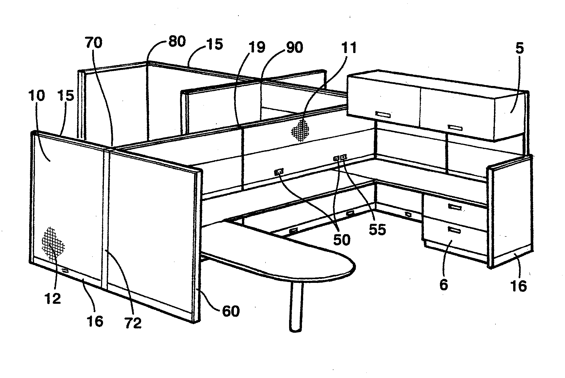
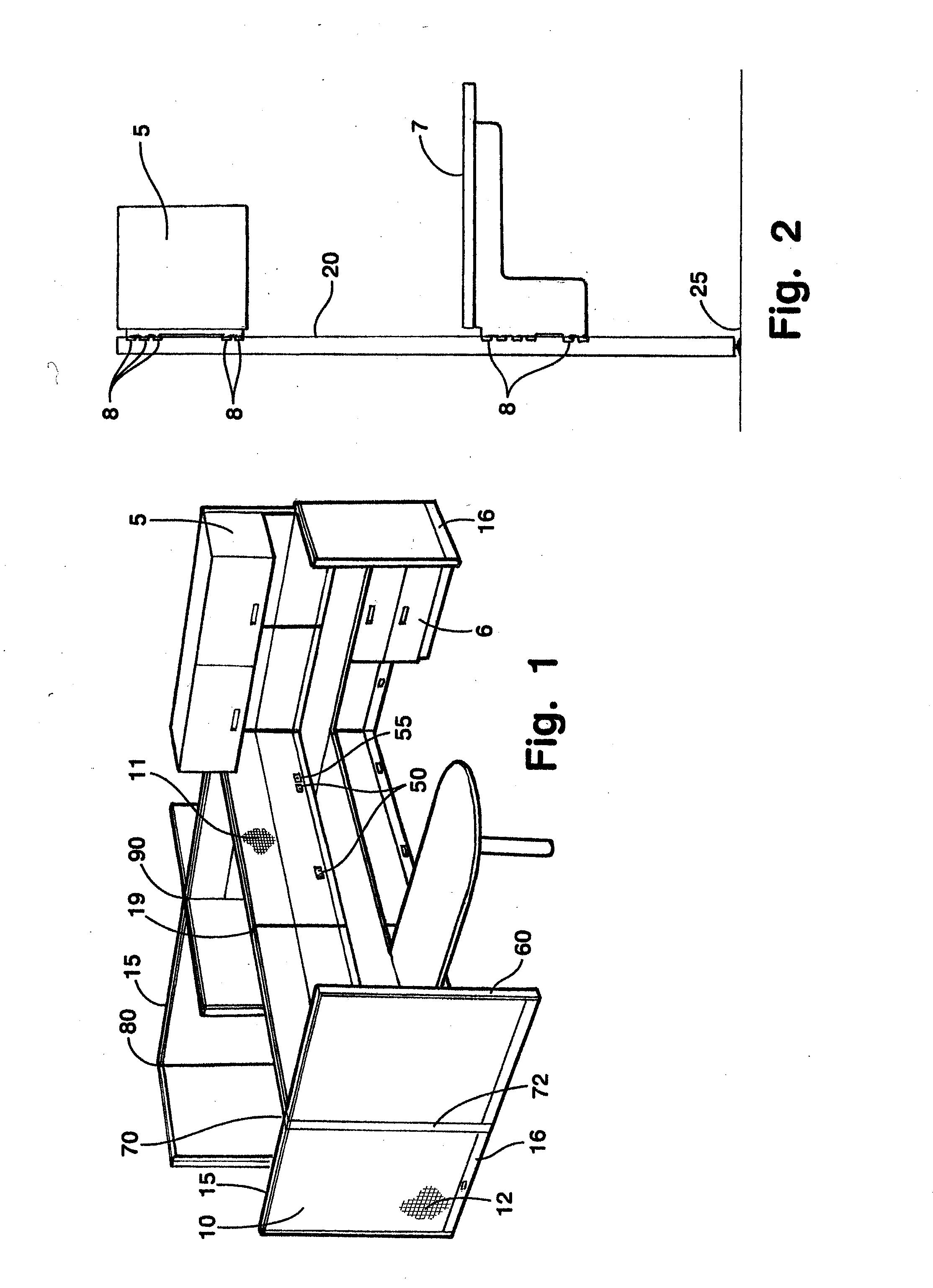
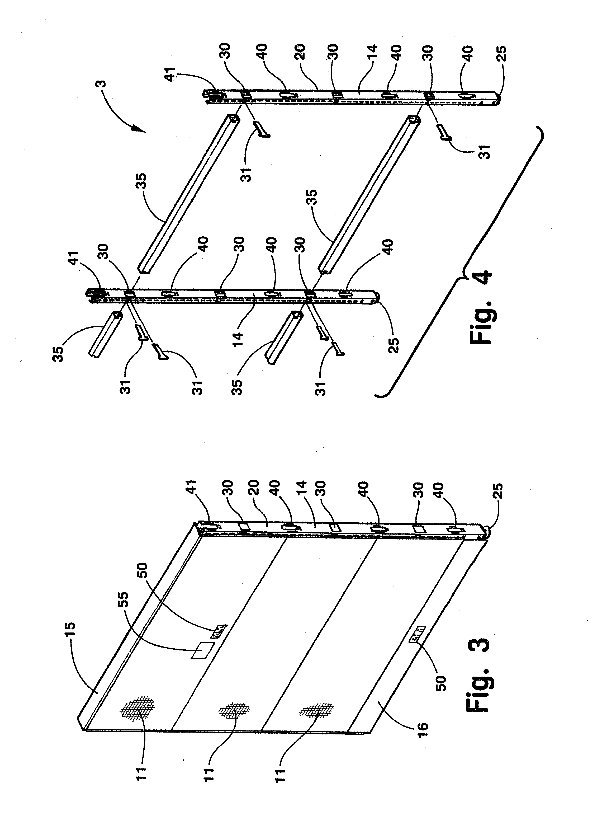
[0011] A knock-down portable partition system has cover panels supported on a post and beam framework designed for quick and easy on-site manual assembly. The framework includes at least two vertical posts and at least two structural beams rigidly, yet detachably interconnecting the vertical posts. Connectors secure the beams to the posts, such that the partition system can be assembled and disassembled manually. The partition system may include utility troughs shaped to retain wires, cabling, etc. therein to provide power and / or communication to the system. The utility troughs have opposite ends shaped to be detachably mounted to the posts.

Problems solved by technology

Since there are two vertical frame members at each panel joint, this type of panel construction results in structural redundancy.
Furthermore, although longer panels typically have a lower cost per unit length, longer panels are difficult to handle, which places a practical limit on the size of the partition panel member that can be shipped and installed as a prefabricated unit.
Since only a single vertical member is needed to provide support and height adjustment, this type of system has redundant structure.
In addition, the rectangular partition panel members are manufactured and shipped as a unit, limiting the size of the partition panel members that can be used.
Thus, there is redundancy in both the post and the beam structures.

Method used


Image

  • Knock-down portable partition system
  • Knock-down portable partition system
  • Knock-down portable partition system

Examples


Embodiment Construction

[0133] For purposes of description herein, the terms “upper”, “lower”, “right”, “left”, “rear”, “front”, “vertical”, “horizontal”, and derivatives thereof shall relate to the invention as oriented in FIG. 1. However, it is to be understood that the invention may assume various alternative orientations and step sequences, except where expressly specified to the contrary. It is also to be understood that the specific devices and processes illustrated in the attached drawings, and described in the following specification are simply exemplary embodiments of the inventive concepts defined in the appended claims. Hence, specific dimensions and other physical characteristics relating to the embodiments disclosed herein are not to be considered as limiting, unless the claims expressly state otherwise.

[0134] The reference numeral 1 (FIG. 1) generally designates a knock-down portable partition system embodying the present invention. The illustrated knock-down portable partition system 1 has ...


PUM


Abstract

A knock-down portable partition system has cover panels supported on a post and beam framework designed for quick and easy on-site manual assembly. The framework includes at least two vertical posts and at least two structural beams rigidly, yet detachably interconnecting the vertical posts. Connectors secure the beams to the posts, such that the partition system can be assembled and disassembled manually. The partition system may include utility troughs shaped to retain wires, cabling, etc. therein to provide power and / or communication to the system. The utility troughs have opposite ends shaped to be detachably mounted to the posts.

Description

CROSS-REFERENCES TO RELATED APPLICATIONS [0001] This application is a continuation of U.S. patent application Ser. No. 11 / 044,843, filed on Jan. 27, 2005, entitled KNOCK-DOWN PORTABLE PARTITION SYSTEM, which is a continuation of U.S. Pat. No. 6,910,306, which is a Continuation-In-Part of U.S. Pat. No. 6,442,909, which is a continuation of U.S. Pat. No. 6,301,846. [0002] U.S. Pat. No. 6,301,846 is a Continuation-In-Part of U.S. Pat. No. 6,009,675, which claims the benefit of U.S. Provisional Application No. 60 / 033,884, filed Dec. 24, 1996. [0003] U.S. Pat. No. 6,301,846 is also a Continuation-In-Part of U.S. Pat. No. 6,079,173, which is a continuation of U.S. Pat. No. 5,899,035. [0004] U.S. Pat. No. 6,910,306 is also a Continuation-In-Part of U.S. Pat. No. 6,546,684, which is a continuation of U.S. Pat. No. 6,276,103, which is a division of U.S. Pat. No. 6,098,358. The present application is also related to commonly assigned, U.S. Pat. No. 6,178,702, entitled FLEXIBLE LIGHT SEAL FOR ...

Claims


Application Information

Patent Timeline
Patent Type & Authority Applications(United States)
IPC IPC(8): E04H1/00A47B21/00A47B83/00E04B2/72E04B2/74
CPCA47B21/06A47B83/001E04B2/7433E04B2002/7461E04B2002/749E04B2002/7466E04B2002/7483E04B2002/7487E04B2002/7488E04B2002/7464
Inventor WAALKES, MICHAEL L.PRESSNELL, MARCUS K.SLAGER, MARK T.SHIELDS, MICHAEL R.KANE, BRIAN J.CHRISTOPHER, ROBINBOYLE, DENNIS J.SEIBER, CHARLES A.SKILLMAN, PETER N.CHANG, JOSEPHHAND, RICHARD S.
Owner STEELCASE INC
Learn More