Combustor of gas turbine and combustion control method for gas turbine

Active Publication Date: 2007-10-04
MITSUBISHI POWER LTD
View PDF12 Cites 40 Cited by
  • Summary
  • Abstract
  • Description
  • Claims
  • Application Information

AI Technical Summary

Benefits of technology

[0041]In the present invention, when the total amount of fuel supplied to the combustor is small as in a speed increasing state or a low load state, fuel is injected only from the fuel injection holes facing the divisional fluid passages of the first group among the fuel injection holes formed in the vane surfaces of the internal swirler vanes. Thus, the concentration of fuel in this limited region does not become excessively low, but becomes higher than the flammability limit concentration. Even in the speed increasing state or low load state, therefore, the occurrence of unburned fuel can be suppressed, and flame holding performance can be improved.
[0042]Moreover, the blocking members for inhibiting outflow of a fluid are disposed in boundary portions betwee

Problems solved by technology

Thus, if the amount of fuel supplied is decreased in the speed increasing state or in the low load state, the concentration of a fuel gas (a mixture of fuel and air) is too low, meaning an ex

Method used


Image

  • Combustor of gas turbine and combustion control method for gas turbine
  • Combustor of gas turbine and combustion control method for gas turbine
  • Combustor of gas turbine and combustion control method for gas turbine

Examples


Example

Embodiment 1

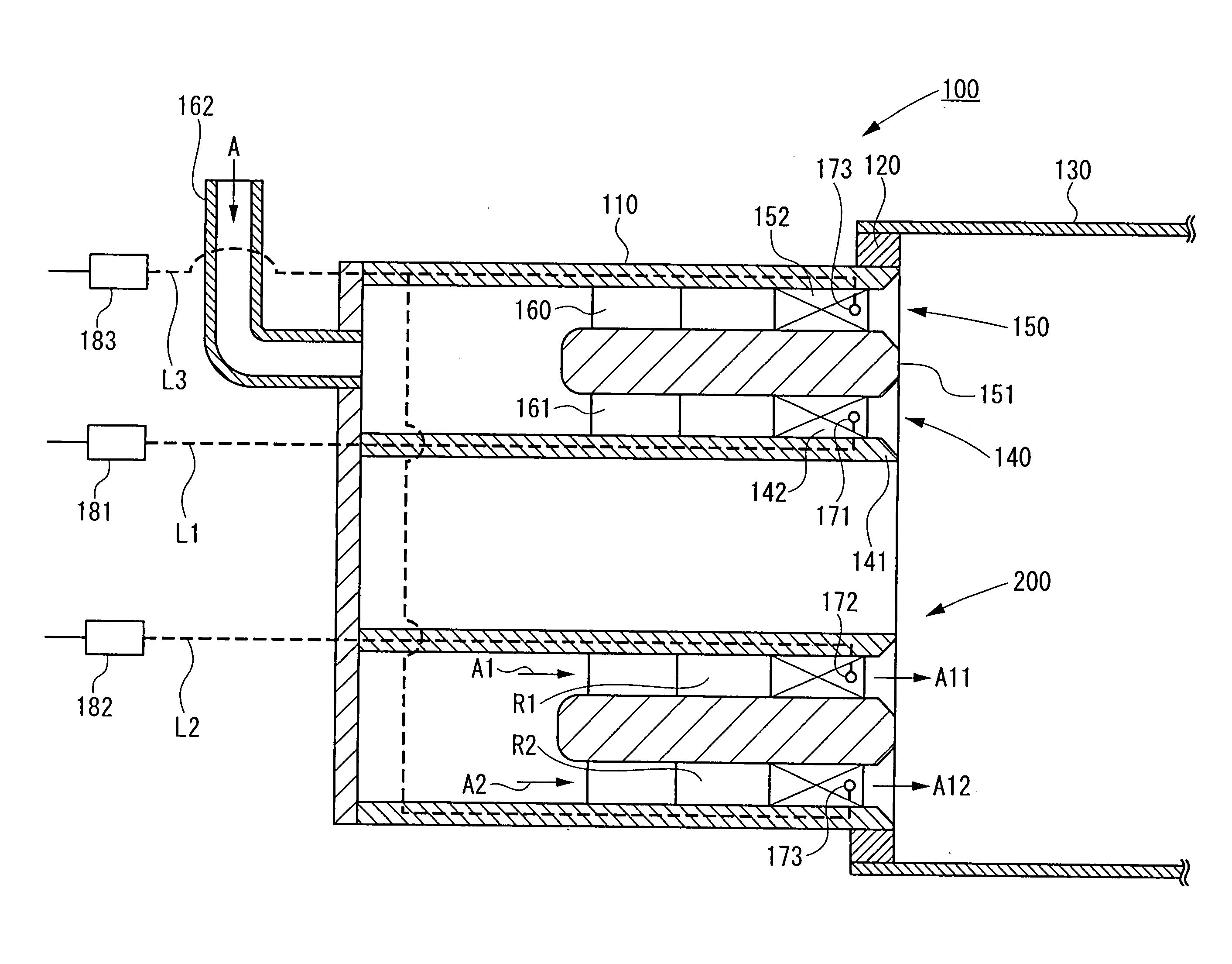
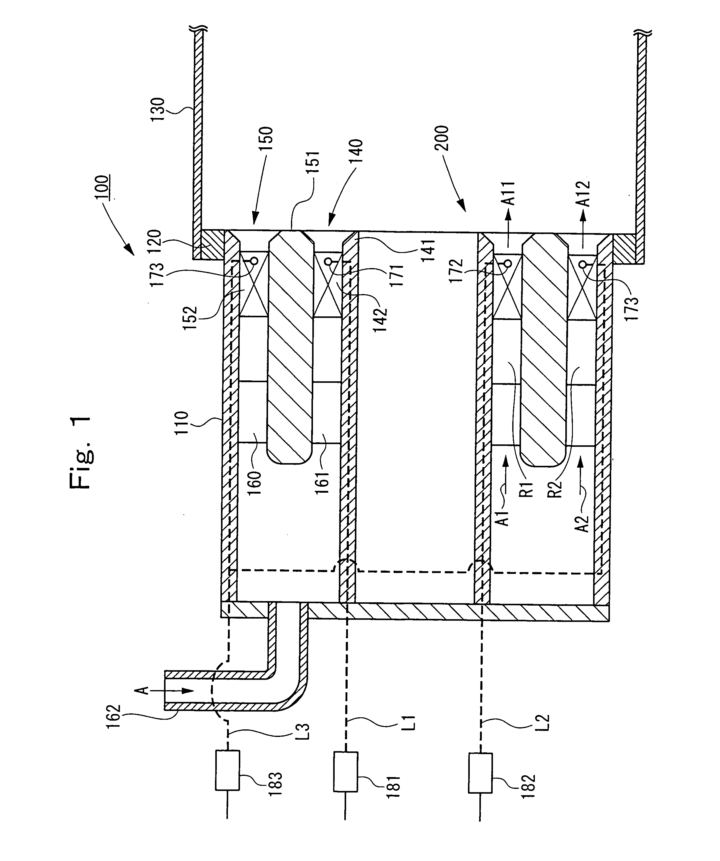
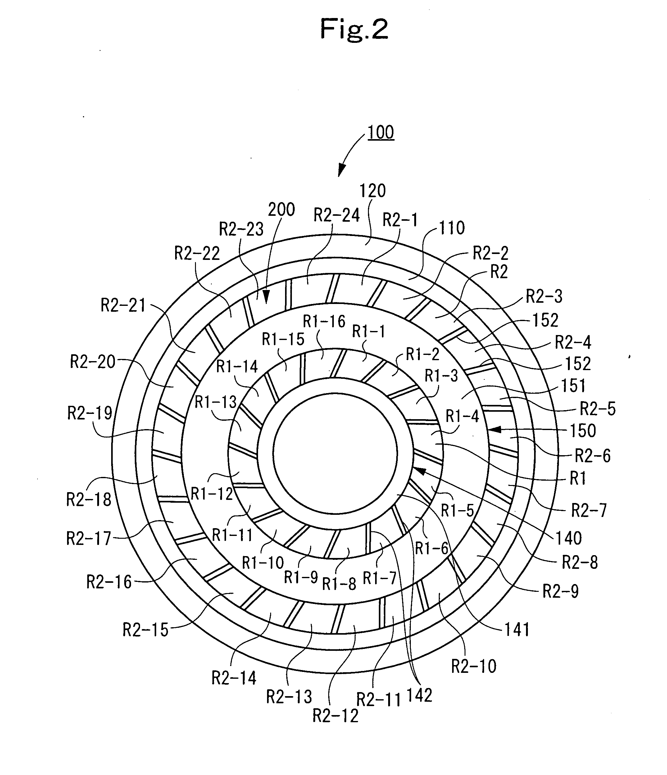
[0057]A combustor 100 of a gas turbine according to Embodiment 1 of the present invention is described with reference to FIG. 1 as a longitudinal sectional view, and FIG. 2 as a front view. The combustor 100 according to this Embodiment 1 is applied to a gas turbine at a high pressure ratio (a pressure ratio of 25 or higher) in the 1700° C. class being newly developed.

[0058]As shown in FIGS. 1 and 2, the rear edge of an inner tube 110 is connected to the leading edge of a transition pipe 130 via a connecting ring 120.

[0059]Inside the inner tube 110, an internal swirler 140 and an external swirler 150 are placed. That is, the internal swirler 140 on the inner peripheral side and the external swirler 150 on the outer peripheral side are disposed concentrically about the central axis of the inner tube 110. The internal swirler 140 and the external swirler 150 constitute a double swirler 200.

[0060]A swirler ring 141 of the internal swirler 140 is of a cylindrical shape, and...

Example

Embodiment 2

[0107]Next, a combustor 100A of a gas turbine according to Embodiment 2 of the present invention will be described with reference to FIG. 6 as a front view.

[0108]In the combustor 100A of Embodiment 2, blocking members H for decreasing the flow areas of the divisional fluid passage R1-8 and the divisional fluid passage R1-16 are provided at the rear edge of the divisional fluid passages R1-8 and R1-16.

[0109]In other words, at the rear edge of the inner tube 110, the blocking members H for inhibiting the outflow of a fluid are disposed at the boundary portions between the divisional fluid passages R1-1 to R1-8 of the first group and the divisional fluid passages R1-9 to R1-16 of the second group.

[0110]Thus, the swirl air flow A11 exiting from the divisional fluid passages R1-1 to R1-7 of the first group, and the swirl air flow A12 exiting from the divisional fluid passages R1-9 to R1-15 of the second group are not mixed in the neighborhood of the rear end of the inner tub...

Example

Embodiment 3

[0116]Next, a combustor 100B of a gas turbine according to Embodiment 3 of the present invention will be described with reference to FIG. 7 as a longitudinal sectional view. This Embodiment 3 has the same basic configuration and uses the same combustion control method as those in Embodiment 1.

[0117]In the Embodiment 3, of the fuel injection holes 171 of the first group, the fuel injection holes 171 facing the divisional fluid passage R1-1 and the divisional fluid passage R1-8 have larger hole diameters. That is, the fuel injection holes 171 facing the divisional fluid passages R1-1 and R1-8 adjacent to the divisional fluid passages R1-9 to R1-16 of the second group among the divisional fluid passages R1-1 to R1-8 of the first group have larger hole diameters.

[0118]In the first group, therefore, the concentration of the fuel gas exiting from the divisional fluid passages R1-1 and R1-8 is higher than the concentration of the fuel gas exiting from the divisional fluid pass...


PUM


Abstract

In a combustor, divisional fluid passages of a first group, and divisional fluid passages of a second group are present on an inner peripheral side, and divisional fluid passages are also present on an outer peripheral side, and swirl air flows are gushed from the divisional fluid passages. When the total amount of fuel supplied to the combustor is small as in a speed increasing state or in a low load state, fuel is injected only into the divisional fluid passages of the first group. Since a fuel injection region is limited to a position on the inner peripheral side, particularly, a specific position, the concentration of a fuel gas comprising a mixture of fuel and air is lean, but is higher than a flammability limit concentration, even when the total amount of fuel is small.

Description

BACKGROUND OF THE INVENTION [0001]1. Field of the Invention[0002]This invention relates to a combustor of a gas turbine, and a combustion control method for a gas turbine, the combustor and the combustion control method being designed to be capable of ensuring stable combustion and suppressing the occurrence of unburned fuel.[0003]More particularly, the combustor and the combustion control method are designed to improve flame holding properties, and suppress the occurrence of unburned fuel, during an operation in which the amount of fuel supplied to the combustor is small, as in a speed increasing state or in a low load state.[0004]2. Description of the Related Art[0005]A gas turbine used in power generation, etc. is composed of a compressor, a combustor, and a turbine as main members. The gas turbine often has a plurality of combustors, and mixes air, which is compressed by the compressor, with fuel supplied to the combustors, and burns the mixture in each combustor to generate a h...

Claims


Application Information

Patent Timeline
IPC IPC(8): F02C3/00
CPCF02C3/14
Inventor SAITO, KEIJIROTANIMURA, SATOSHIYUASA, ATSUSHISAITO, TOSHIHIKO
Owner MITSUBISHI POWER LTD
Why Eureka
Try Eureka