Gas turbine combustor

Active Publication Date: 2014-03-13
MITSUBISHI POWER LTD
View PDF0 Cites 13 Cited by
  • Summary
  • Abstract
  • Description
  • Claims
  • Application Information

AI Technical Summary

Benefits of technology

[0022]According to the present invention, a gas turbine combustor, in a gas turbine that uses a low BTU gas such as a blast furnace gas as a main fuel, that enables a startup with a high calorific gas fuel such as an LNG and can improve stable combustion in multi-fuel combustion of a high BTU gas and a low BTU gas, can be realized.
[0023]Further, according to an embodiment of the present invention, since a high BTU gas hole is formed in an exit flow path in at least either the gas hole or the air hole in a low BTU gas fired burner, it becomes possible to burn a high BTU

Problems solved by technology

When gas holes of a low BTU gas fired burner are used to burn an LNG, the jet flow velocity of the fuel is extremely lowered and the flame holding performance is thereby significantly reduced, making it difficult to burn the LNG by using low BTU gas holes.
Since the theoretical amount of air for the LNG is larger than that of low BTU gases, if the LNG is burned by using a burner that stably burns a low BTU gas in a state in which the amount of air supplied to the burner is suppressed, air insufficiency is likely to occur.
H

Method used


Image

  • Gas turbine combustor
  • Gas turbine combustor
  • Gas turbine combustor

Examples


Example

Embodiment 1

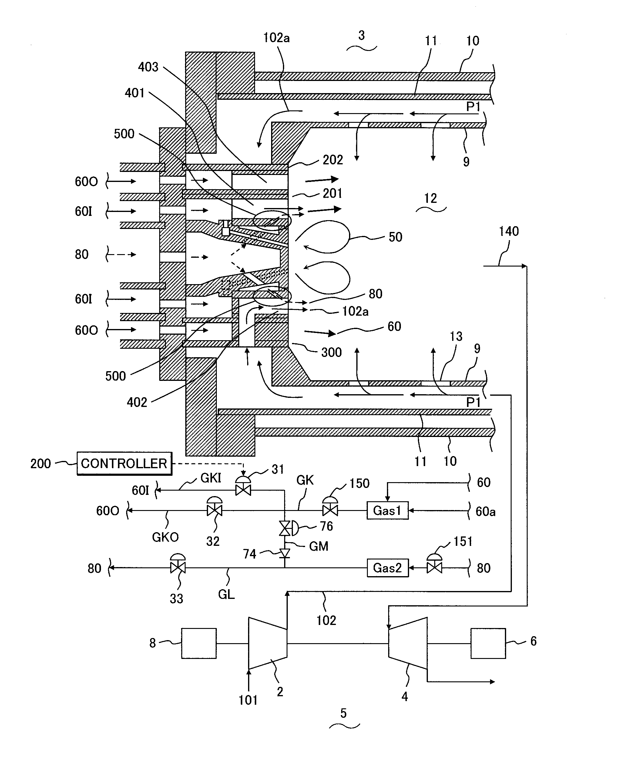
[0036]FIG. 1 is an enlarged cross sectional view of paths and a combustor in a gas turbine in an embodiment of the present invention. An embodiment of the present invention uses a combustion method in which the main fuel is a low BTU fuel and a startup fuel is a high calorific fuel. In this embodiment, a blast furnace gas was used as an example of the low BTU fuel and an LNG was used as an example of the high calorific fuel.

[0037]In FIG. 1, main units that constitute a gas turbine, fuel paths, and an enlarged structure of a combustor are shown. The main units that constitute a gas turbine are a compressor 2, a combustor 3, a turbine 4, an electric power generator 6, a startup motor 8, etc. as shown at the bottom in FIG. 1.

[0038]The gas turbine 5 compresses air 101 that the compressor 2 inhaled from the atmosphere, supplies compressed air 102 to the gas turbine combustor 3, generates thermal energy by mixing and burning a fuel and air in the combustor 3, and supplies a co...


PUM


Abstract

A gas turbine combustor includes a burner disposed upstream of the combustion chamber for supplying a gas and air to an interior of the combustion chamber to hold a flame provided with a first swirler in which a gas hole and an air hole are alternately formed in a circumferential direction. A first gas is supplied to the gas hole in the first swirler and air is supplied to the air hole. A swiveling flow path is formed in the gas hole and the air hole in the burner to swivel the gas and the air and supply the gas and the air to the interior of the combustion chamber, a second gas hole is formed in the swiveling flow path in at least one of the air hole and the gas hole, and a second gas is supplied through the second gas hole.

Description

CLAIM OF PRIORITY[0001]The present application claims priority from Japanese patent application JP 2012-194783 filed on Sep. 5, 2012, the content of which is hereby incorporated by reference into this application.BACKGROUND OF THE INVENTION[0002]1. Field of the Invention[0003]The present invention relates to a gas turbine combustor which stably burns a flame-retardant gas that has a high content of nitrogen (N2), carbon dioxide (CO2) or water vapor, such as a blast furnace gas, a coal gasified gas or a biomass gasified gas, and is a low calorific gas (low BTU gas).[0004]2. Description of Related Art[0005]In general, a low BTU gas has a low flame temperature and a low burning velocity when compared with an LNG (liquefied natural gas), which is a main fuel of the gas turbine, so the low calorific gas is a fuel that is hard to burn. However, its low NOx emissions during combustion are one of features, so a method of using a low BTU gas is an issue.[0006]A typical example of this low BT...

Claims


Application Information

Patent Timeline
IPC IPC(8): F23R3/36F23R3/14
CPCF23R3/14F23R3/36F23R3/12F23R3/286F23D14/24F23D2204/00F23D2900/00008F23R2900/00002
Inventor KOIZUMI, HIROMISEKIGUCHI, TATSUYAHAYASHI, AKINORIYOSHIDA, SHOHEI
Owner MITSUBISHI POWER LTD
Why Eureka
Try Eureka