A Secondary Air Arrangement Device for Garbage Incinerator

A waste incinerator and secondary air technology, applied in the direction of incinerators, combustion methods, combustion types, etc., can solve the problems affecting the stiffness of the secondary air jet, the decrease of the secondary air injection wind speed, the optimization of unfavorable air flow organization and the adjustment of combustion, etc. problems, achieve the effects of strengthening mixing and residence time, increasing combustion rate, and expanding fuel adaptability

Active Publication Date: 2015-12-09
SOUTH CHINA UNIV OF TECH
View PDF6 Cites 0 Cited by
  • Summary
  • Abstract
  • Description
  • Claims
  • Application Information

AI Technical Summary

Problems solved by technology

In addition, when the moisture content of the garbage entering the furnace is obviously high, such as in the southern spring, the sharp drop in the calorific value of the garbage will lead to a sharp drop in the corresponding secondary air volume. If the original number of secondary air nozzles is maintained, the wind speed of the secondary air injection will It will be greatly reduced, affecting the jet stiffness of the secondary air, which is not conducive to the optimization of airflow organization and combustion adjustment in the furnace

Method used


Image

  • A Secondary Air Arrangement Device for Garbage Incinerator
  • A Secondary Air Arrangement Device for Garbage Incinerator
  • A Secondary Air Arrangement Device for Garbage Incinerator

Examples


Embodiment

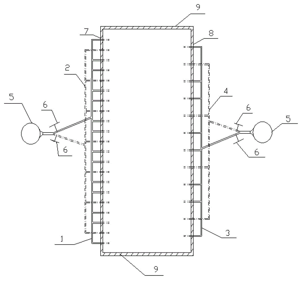
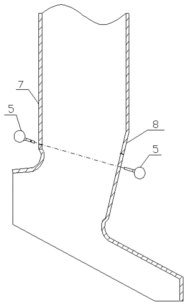
[0024] Such as figure 1 , 2 shown. The secondary air layout device of the garbage incinerator of the present invention includes a secondary air pipe 5, a secondary air door 6, a front wall 7, a rear wall 8, a side wall 9, a first group of secondary air nozzles 1 on the front wall, and a second air nozzle on the front wall. Two groups of secondary air nozzles 2, the first group of secondary air nozzles 3 on the rear wall, and the second group of secondary air nozzles 4 on the rear wall are characterized in that: the first group of secondary air nozzles 1 on the front wall and the second group of secondary air nozzles on the front wall The arrangement position of the two groups of secondary air nozzles 2 is 0.61m~1m away from the entrance of the first flue; the first group of secondary air nozzles 1 on the front wall and the second group of secondary air nozzles 2 on the front wall are on the same plane, and The angle between the injection angle and the inclined surface of the...


PUM


Abstract

The invention discloses a secondary air arrangement device of a garbage incinerator. The secondary air arrangement device comprises a first group and a second group of secondary air nozzles on a front wall, and a first group and a second group of secondary air nozzles on a back wall; the arrangement positions of the first group and the second group of secondary air nozzles on the front wall are 0.61 m to 1 m to away from a first flue inlet; the first group and the second group of secondary air nozzles on the front wall are positioned on the same plane; an included angle between the spraying angles of the first group and the second group of secondary air nozzles on the front wall and an oblique plane of the back wall is 90 degrees; and the arrangement positions of the first group and the second group of secondary air nozzles on the back wall and the first group and the second group of secondarily air nozzles on the front wall are on the same plane and form secondary air convection between the front wall and the back wall. When the heat value of garbage entering the incinerator is decreased greatly, the second groups of secondary air nozzles on the front wall and the back wall are closed, so that the higher flow speed of secondary air is maintained in a condition that a total air quantity is reduced. By regulating the proportion of the secondary air and the opening and the closure of the secondary air in each group, the rigidity of the jet current of the secondary air is maintained; the in-time afterburning is realized; the air-flow organization in the incinerator is optimized; a flame kernelcenter is guaranteed to be positioned in a central area; and a water wall is prevented from generating a local high-temperature condition.

Description

technical field [0001] The invention relates to a garbage incinerator, in particular to a secondary air arrangement device for a garbage incinerator. Background technique [0002] The rapid development of China's urbanization process brings convenience to people's lives, but it also faces a series of problems. Urban waste disposal is becoming a major problem in China's urbanization. With the rising cost of land, the economic benefits of waste disposal methods such as composting and sanitary landfill continue to decline. At the same time, the secondary pollution of soil and groundwater caused by composting and sanitary landfill has also attracted people's attention. Waste incineration power generation treatment has the advantages of strong capacity reduction, remarkable resource utilization effect, and small footprint, and is becoming an important development direction of urban domestic waste treatment in my country. [0003] At present, there are many types of waste incine...

Claims


Application Information

Patent Timeline
Patent Type & Authority Patents(China)
IPC IPC(8): F23G5/44
Inventor 马晓茜唐玉婷赖志燚
Owner SOUTH CHINA UNIV OF TECH
Why Eureka
Try Eureka