[0004]The present invention therefore deals with the problem of stating an improved or at least alternative embodiment for a residual gas burner of the type mentioned at the outset, which is characterized in particular through an improved efficiency and / or through an easy and cost-effective design.
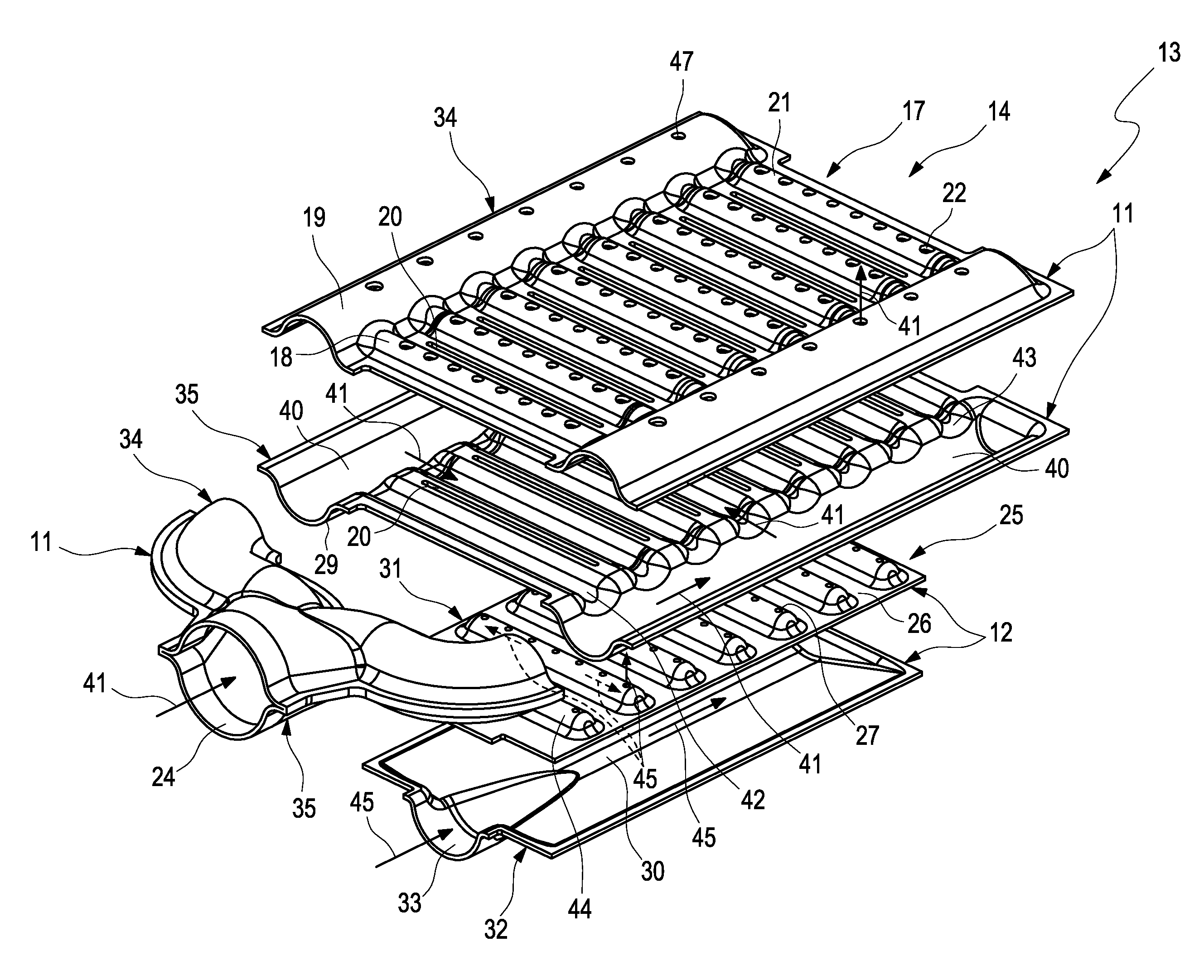
[0006]The present invention is based on the general idea of equipping a residual gas burner for a fuel cell system with two educt gas feeds, each of which comprise at least one outlet opening for letting out a respective educt gas into a combustion chamber of the residual gas burner, and arranging the outlet openings of the one educt gas closer to the combustion chamber than the outlet openings of the other educt gas. Because of this, an improved mixing-through of the respective educt gases prior to the combustion takes place, which leads to an improved and more stable combustion or flame within the combustion chamber and consequently improves the efficiency of the residual gas burner. The modulation capability of the residual gas burner is also improved towards higher lambda values because of this.
[0010]With a preferred embodiment, the second outlet channel system is arranged on the first bottom surface of the first outlet channel system. Practically, the first outlet channel system and the second outlet channel system are designed as separate components. Preferred is an embodiment, wherein the respective educt gas feeds and thus the respective outlet channel systems are designed as separate components. The arrangement of the second outlet channel system and thus of the second top surface on the first bottom surface of the first outlet channel system means in particular that the educt gas feeds are directly adjacent. The educt gas feeds in this case can be mechanically connected to each other, wherein the connection between the educt gas feeds can be realised in any way, provided they are suitable for the temperatures and pressures that are present there or in the combustion chamber. The separate design of the respective educt gas feeds has as a consequence in particular that the residual gas burner can be assembled from individual modules. This leads to a simplified and thus cost-effective production of the residual gas burner. In addition, the feeds or the channel systems can be structured in a simple manner, which facilitates a cost-effective production.
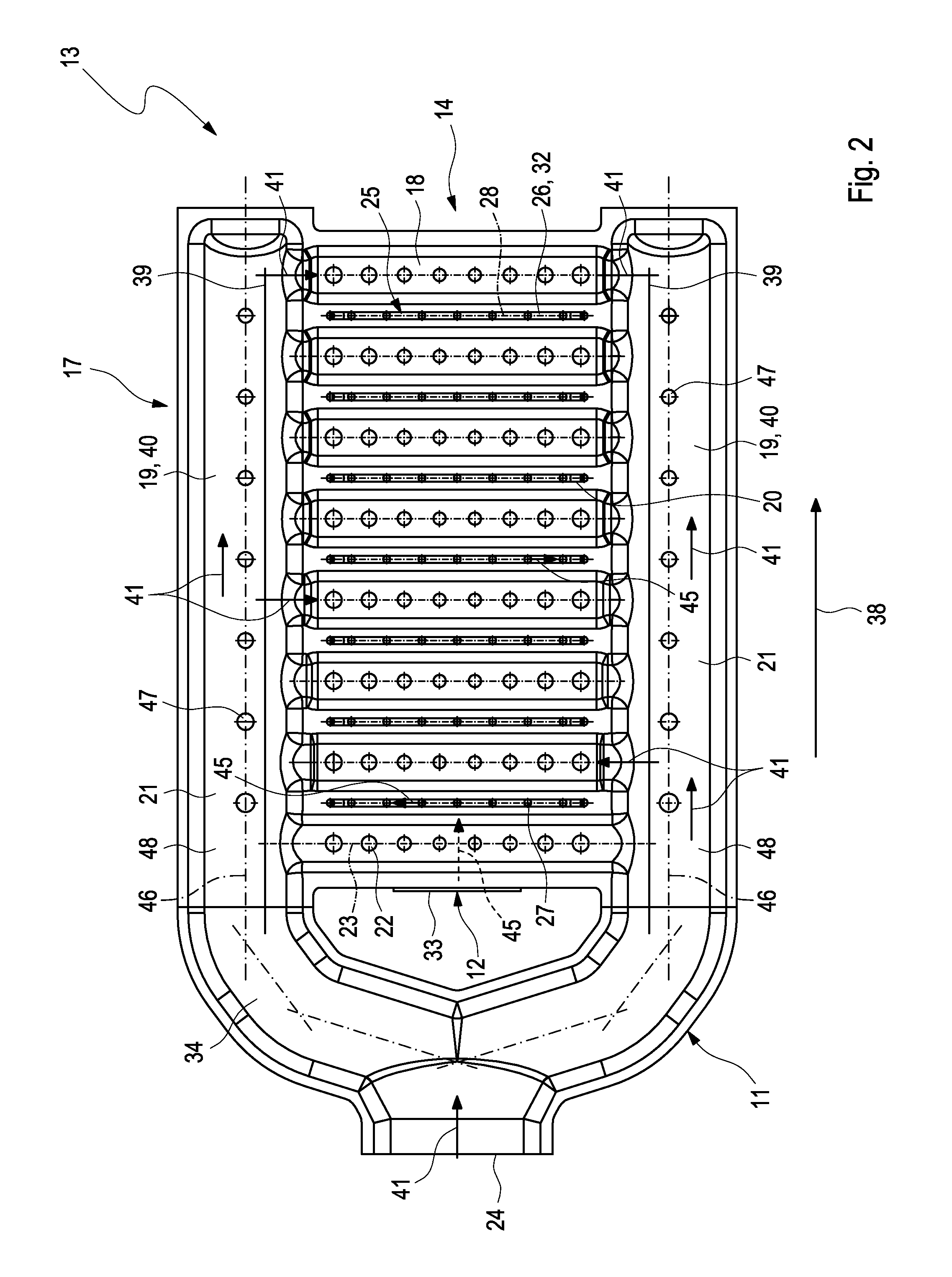
[0015]Additionally, the respective first feed channel can comprise at least one bypass opening, which is arranged laterally or in a marginal region of the combustion chamber or connected to a bypass path leading passed the combustion chamber. The bypass openings in particular serve the purpose of reducing the flow rate of the first educt gas into the combustion chamber. Within a combustion chamber of the residual gas burner, a marginal region can be provided laterally of the combustion chamber, which is not assigned any second outlet openings, so that there only the bypass openings are provided and only the first educt gas enters into the marginal region. The educt gas flow entering the combustion chamber via the bypass openings is then guided laterally along walls of the combustion chamber enclosing the combustion chamber, which means a thermal relief of the combustion chamber walls. Optionally, at least one bulkhead can be arranged in the combustion chamber, which runs parallel to a combustion chamber wall and in at least one region adjoining the first surface separates the marginal region from the combustion chamber. Distally to the first surface, the respective bulkhead can be overflowable, so that the respective marginal region there is fluidically connected to the combustion chamber. Insofar as the respective marginal region is separated from the combustion chamber through at least one such bulkhead, the marginal region includes the bypass path at least partially passing by the combustion chamber. The bypass openings are preferentially arranged also on the first top surface.
[0020]Preferred is an embodiment, wherein both the first outlet channel system or the first educt gas feed as well as the second outlet channel system or the second educt gas feed are produced in shell design. The respective shells, i.e. the respective top surface shells and / or the respective bottom shells are produced for example through a deep-drawing method. The respective shells can be formed from sheet metal, in particular of iron metals and / or light metals through the deep-drawing and subsequently connected to each other. As examples for connecting possibilities of the respective shells, welding, soldering, screwing or gluing are pointed out here, wherein any types of the connection of the respective associated shells are conceivable provided these connection types are suitable for the thermodynamic conditions prevailing in the combustion chamber. Through the shell design of the shells formed in particular from sheet metal, a cost-effective production of the educt gas feeds and thus of the residual gas burner is possible. In addition, the weight of the residual gas burner is reduced because of this, which is advantageous in particular with mobile applications of the associated fuel cell system.
[0023]Alternatively or additionally, the homogenisation of the flow rate of the respective educt gas can be realised through adapting the size of the associated channel inlets. The respective channel inlets can for example comprise a constriction, wherein the throttling effect of the constrictions along the flow direction of the associated educt gas in the feed channel supplying the channels or in the feed channels supplying the channels, increases. In other words, the flow cross section made available through the channel inlets becomes smaller along the flow direction in the associated feed channels, so that the pressure in the educt gas which increases through the damming-up can be offset along the flow direction.

