
Residual gas burner

a gas burner and residual gas technology, applied in the direction of combustion types, electrochemical generators, lighting and heating apparatuses, etc., can solve the problems of high cost, low efficiency, and high cost of residual gas burners, and achieve the effect of improving efficiency and easy and cost-effective design

Active Publication Date: 2013-03-28
EBERSPAECHER CLIMATE CONTROL SYST GMBH & CO KG
View PDF1 Cites 3 Cited by
  • Summary
  • Abstract
  • Description
  • Claims
  • Application Information

AI Technical Summary

Benefits of technology

The present invention is about an improved residual gas burner for a fuel cell system that has better efficiency and is easier to design. The improvement is achieved by equipping the burner with two educt gas feeds, each with its own outlet opening closer to the combustion chamber. This allows for better mixing of the educt gases before the combustion, resulting in a more stable flame and improved efficiency. The second outlet channel system is designed as a separate component from the first, making it easier to assemble and cost-effective. The residual gas burner can also have a bypass opening to reduce the flow rate of the educt gas into the combustion chamber. The size of the channel inlets can be reduced to homogenize the flow rate of the educt gas. Overall, this invention provides an improved and cost-effective residual gas burner for fuel cell systems.

Problems solved by technology

Disadvantageous here is that the residual gas burner, in particular due to a poor mixing-through of the educt gases in the combustion chamber, has a low efficiency.
In addition, such residual gas burners are very heavy and through their design, are complex to manufacture.

Method used


Image

  • Residual gas burner
  • Residual gas burner
  • Residual gas burner

Examples


Embodiment Construction

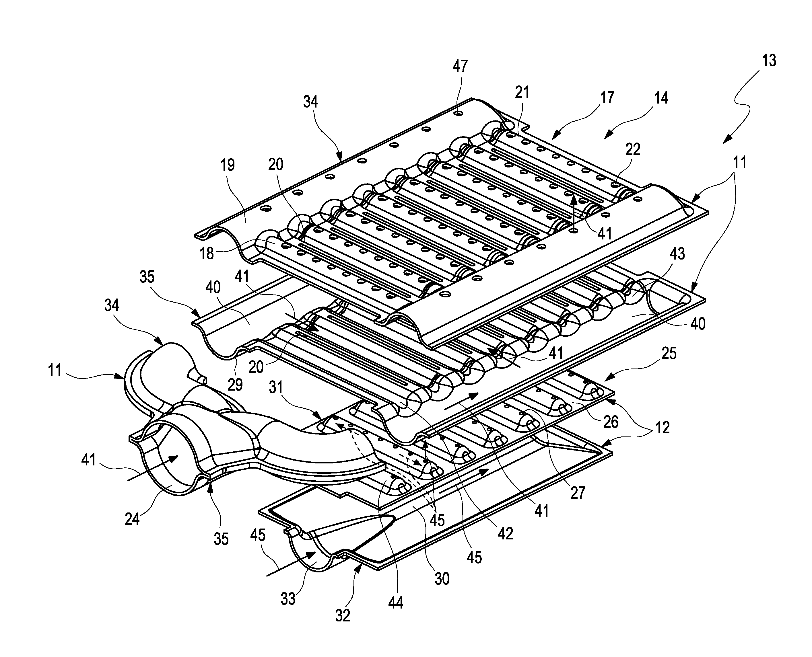
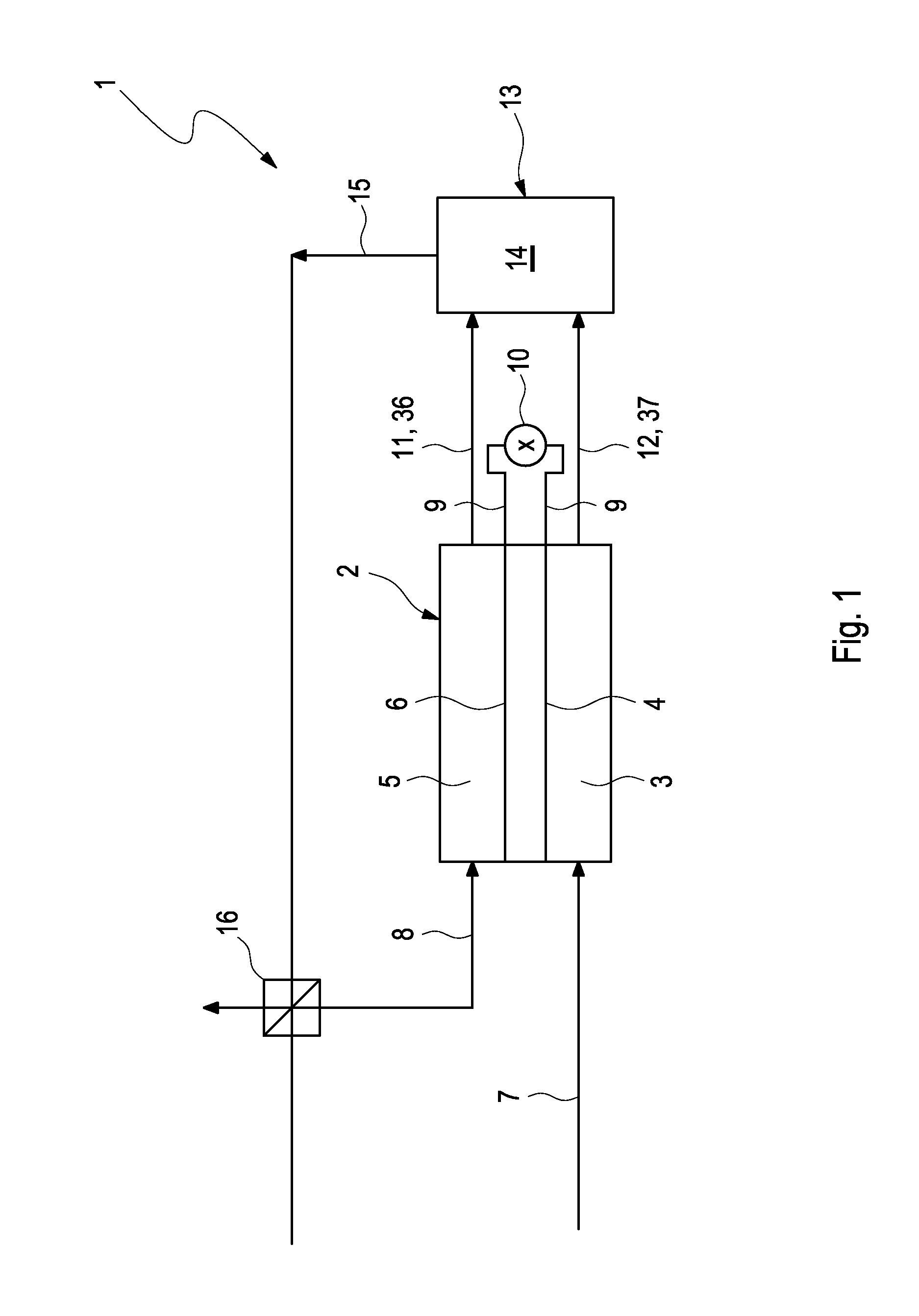
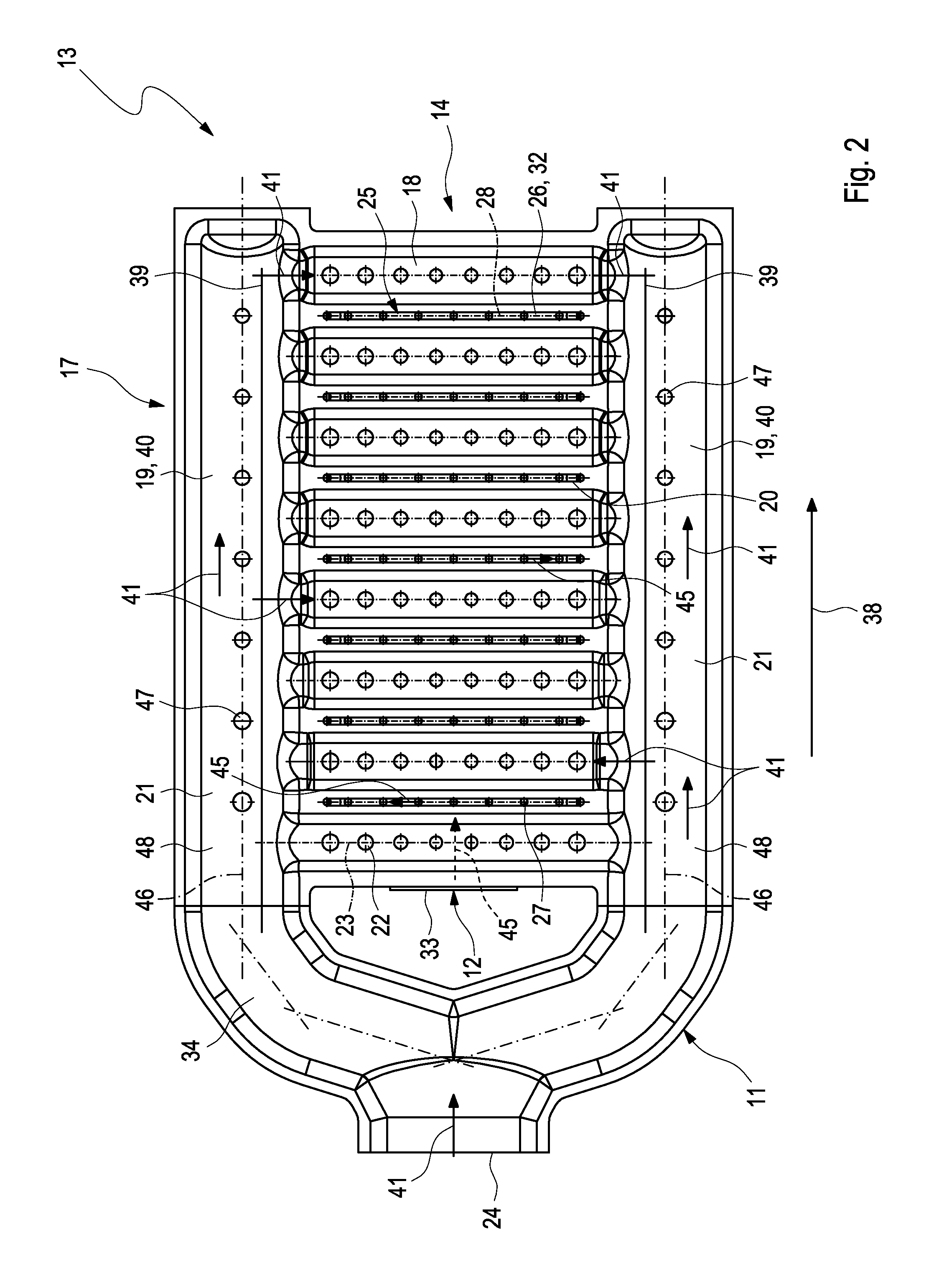
[0041]According to FIG. 1, a fuel cell system 1 comprises at least one fuel cell 2, which on an anode side 3 comprises an anode 4 and on a cathode side 5 comprises a cathode 6. For operating the fuel cell system 1, the anode 4 is supplied with an anode gas and the cathode 6 is supplied with a cathode gas. To this end, an anode gas feed 7 is provided, which feeds the anode gas to the anode 4 on the anode side 3. In addition, a cathode gas feed 8 is provided, which feeds the cathode gas to the cathode 6 on the cathode side 5. The fuel cell 2 converts the chemical energy that is created during the chemical reaction of the cathode gas and of the anode gas into electrical energy and feeds the electrical energy for example in the form of an electrical voltage to an electric consumer 10 by means of electrical lines 9. In the process, anode waste gas generated on the anode side 3 and cathode waste gas on the cathode side 5. The cathode waste gas and the anode waste gas are fed to a residual...


PUM

PropertyMeasurementUnit
sizeaaaaaaaaaa
flow ratesaaaaaaaaaa
electrochemicalaaaaaaaaaa

Abstract

The present invention relates to a residual gas burner (13) for a fuel cell system (1) having to educt gas feeds (11, 12) for feeding an educt gas each to a combustion chamber (14) of the residual gas burner (13). An improved operation of the residual gas burner (13) is obtained when the educt gas feeds (11, 12) each comprise outlet openings (22, 27), wherein the outlet openings (22, 27) face the combustion chamber (14) and the outlet openings (22, 27) of one of the educt gas feeds (11, 12) face a first bottom surface (29) of the other educt gas feed (11, 12).In addition, the invention relates to a fuel cell system (1) having such a residual gas burner (13).

Description

CROSS-REFERENCE TO RELATED PATENT APPLICATION[0001]This patent application claims priority to German Application No. 102011083407.9, filed Sep. 26, 2011, the entire teachings and disclosure of which are incorporated herein by reference thereto.FIELD OF THE INVENTION[0002]The present invention relates to a residual gas burner for a fuel cell system and to a fuel cell system having such a residual gas burner.BACKGROUND OF THE INVENTION[0003]A residual gas burner is usually part of a fuel cell system. The fuel cell system additionally comprises at least one fuel cell, which comprises an anode and a cathode. For operating the fuel cell, an anode gas for the anode and a cathode gas for the cathode are necessary, which are fed to the cathode and to the anode respectively. Through the electrochemical reactions which take place in and / or on the anode and the cathode during the operation of the fuel cell, an anode waste gas and a cathode waste gas develop. The residual gas burner serves for ...

Claims


Application Information

Patent Timeline
Patent Type & Authority Applications(United States)
IPC IPC(8): H01M8/06
CPCY02E60/50F23G7/06F23D14/06F23D14/22F23D14/02H01M8/04022
Inventor BRANDT, SAMUEL
Owner EBERSPAECHER CLIMATE CONTROL SYST GMBH & CO KG
Learn More