
Method for assisting in igniting low-volatile coal in burning by adding oxygen

A low-volatility, low-volatility technology, applied in the field of ignition systems, can solve the problems of low volatile matter, oxygen addition ratio, no detailed regulations on the structure, and low volatile matter, so as to speed up the combustion speed and increase the adaptability of coal types , optimize the combustion effect

Inactive Publication Date: 2015-04-15
NORTH CHINA ELECTRIC POWER UNIV (BAODING)
View PDF9 Cites 0 Cited by
  • Summary
  • Abstract
  • Description
  • Claims
  • Application Information

AI Technical Summary

Problems solved by technology

[0003] At present, the micro-oil ignition technology has been widely used in pulverized coal boiler power plants, and the technology is relatively mature, but generally the adaptability to lean coal and anthracite is not very good
This is due to the low volatile content of lean coal and anthracite coal, and the ignition of its pulverized coal requires higher temperature and energy to promote the pyrolysis of pulverized coal particles into volatiles and coke, and ignites the volatiles, and then ignites the coke. The limited ignition energy and the low volatile matter of lean coal make the energy generated by volatile matter combustion low in the initial stage of combustion, which in turn makes the ignition effect of general pulverized coal micro-oil ignition burners not good for low volatile matter coal.
In the application number 201110086497.X, named "Low Volatile Pulverized Coal Burner", a pulverized coal channel is formed between the central air duct of the first-stage combustion chamber and the coal air duct, and the central air duct is fixed outwards in sequence with coaxial fixed shafts. The air flow pipe is obliquely fixed swirling air pipe, which communicates with the primary main pipe respectively through the pipe, and a cover is installed on the nozzle, which is suitable for the use of power station boilers with lean coal and anthracite coal. The air circulates in the gas channel without supplement The setting of the oxygen pipeline; in the patent application number 201010185480.5, the name is "an oxygen-enriched burner", the burner is a burner when the boiler is under a basic load, and oxygen is directly injected into the furnace through the channel; in the application number It is 200710156019.5, in the patent titled "Multiple oil guns tangentially arranged micro-oil ignition pulverized coal burner", the ignition burner heats the ignition inside the ignition burner through the small oil guns arranged tangentially; in the application number 200920350642.9, the name In the patent of "Powdered Coal Burner with Oxygen-enriched Partial Combustion Support", oxygen is fed into the preheating chamber or precombustion chamber to support combustion, but there are no detailed regulations on the oxygen addition ratio and structure

Method used


Image

  • Method for assisting in igniting low-volatile coal in burning by adding oxygen
  • Method for assisting in igniting low-volatile coal in burning by adding oxygen
  • Method for assisting in igniting low-volatile coal in burning by adding oxygen

Examples


Embodiment 1

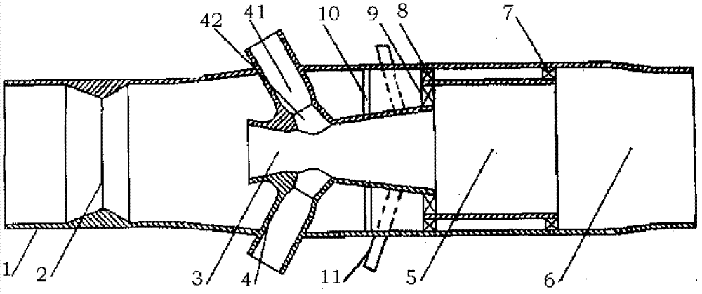
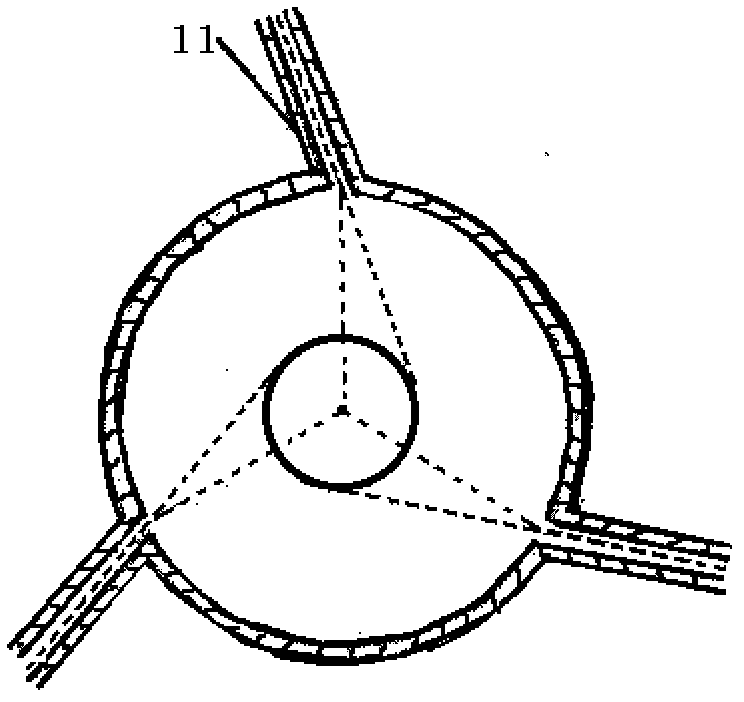
[0012] Low volatile oxygen supplementary micro-oil ignition burner, such as figure 1 As shown, the combustion chamber oxygen supplement micro-oil ignition burner includes four parts: a pulverized coal concentrator, a pulverized coal grading combustion chamber, an oil gun and an oxygen supplement tube. A pulverized coal concentrator 2 with a gradually reduced inner diameter is arranged on the inner wall of the casing 1 near the inlet section (primary air inlet). The back of the pulverized coal concentrator 2 is connected to the three-stage combustion chamber, and the combustion chambers are connected to each other by supporting ribs. The first-stage combustion chamber 3 is connected to the second-stage through the first-level rear rib 9 and the first-level front rib 10 Connection and fixing of the combustion chamber 5, the second-stage combustion chamber is fixed by the second-stage rear rib 7, the second-stage front rib 8 and the first-stage rear rib 9 of the first-stage combust...

Embodiment 2

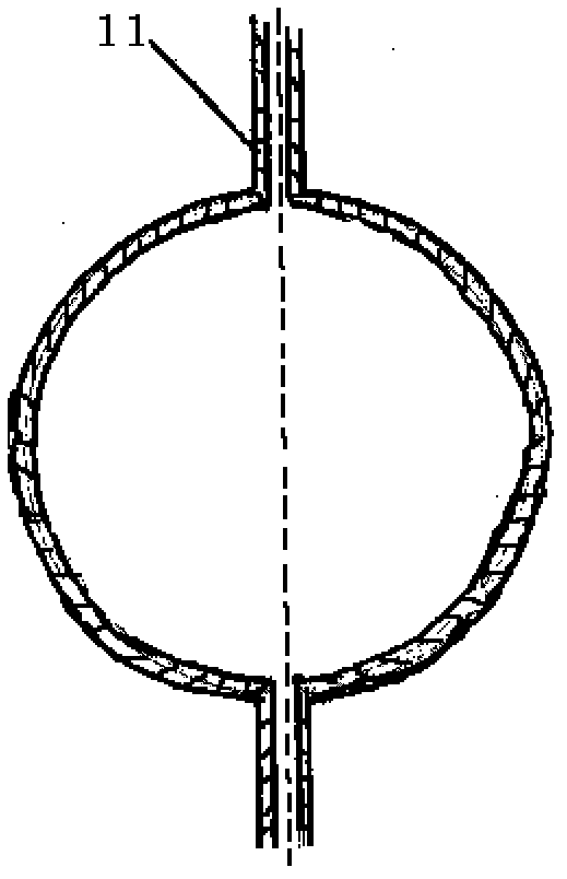
[0014] The difference between Example 2 and Example 1 lies in the way of adding oxygen supplement tube, such as image 3 As shown in the projected cross-sectional schematic diagram of the middle oxygen supplement tube entering the burner inlet, the oxygen supplement tube in Embodiment 2 adopts two oxygen supplement tubes, and the oxygen supplement tube enters the burner in a hedging manner. The two oxygen supplement tubes of Embodiment 2 can also be arranged in a tangential radial direction, and the angle between the axis of the oxygen supplement tube and the normal line of the point is 10-20° in the tangential arrangement. Other aspects are basically the same as Example 1.


PUM


Abstract

The invention belongs to ignition system range, and particularly relates to a method for assisting in igniting low-volatile coal in burning by adding oxygen. Firstly, an existing low-volatile oxygen supplementation tiny-oil ignition burner is used, three stages of burning chambers are arranged in a shell, all igniting chambers and flame guiding tubes are controlled to be axially inclined towards the primary burning chamber by the same included angle of 60 degrees, and all oxygen supplementation tubes are controlled to be axially inclined towards the primary burning chamber by the same included angle of 75-80 degrees. Secondly, oxygen-enriched airflow enters the middle rear of the primary burning chamber obliquely along the oxygen supplementation tubes, burning of low-volatile pulverized coal is promoted, coal adaptability of tiny-oil ignition is enhanced, oil flames are stabilized, disturbed heating of coal stream in the primary burning chamber is increased, and burning is optimized. The oxygen supplementation tubes supplement oxygen to the middle rear of the primary burning chamber, burning is accelerated, burning of the low-volatile pulverized coal is enhanced and stabilized, coal adaptability of tiny-oil ignition is further enhanced, and the requirements of a boiler burning the low-volatile coal on tiny-oil ignition and low-load stable burning are met.

Description

Technical field [0001] The invention belongs to the scope of an ignition system, and particularly relates to a method for adding oxygen to assist the combustion of low-volatile coal. Background technique [0002] With the continuous growth of my country's economy, my country's energy development is facing many challenges, especially the economic growth rate and economic structure directly affect the growth rate of electricity demand. In my country's current power structure, thermal power accounts for a large proportion. By the end of 2008, thermal power accounted for 75.87% of the total capacity. The direct energy sources of thermal power are coal and petroleum, and oil consumption is mainly in the ignition phase and low-load stable combustion process. The ignition and stable combustion of pulverized coal boilers consume a lot of fuel, resulting in increasing consumption of high-quality fuel. According to statistics, a 125MW unit boiler needs 15 tons of fuel to start up, while ...

Claims


Application Information

Patent Timeline
Patent Type & Authority Patents(China)
IPC IPC(8): F23D1/00F23L7/00
CPCY02E20/34
Inventor 付忠广张永生
Owner NORTH CHINA ELECTRIC POWER UNIV (BAODING)
Learn More