Flying Lead Connector and Method for Making Subsea Connections

a technology of flying lead connector and subsea connection, which is applied in the direction of underwater drilling, drilling machines and methods, and wellbore/well accessories, etc. it can solve the problems of high cost of drilling and maintenance of deep and remote offshore wells, large pressure drop across the length of hoses, and inability to meet the requirements of rov involvement and power requirements, so as to reduce the installation time and reduce the power rating. , the effect of reducing the involvement of rov and reducing the impa

Inactive Publication Date: 2007-10-04
FONTENETTE LIONEL M +1
View PDF34 Cites 34 Cited by
  • Summary
  • Abstract
  • Description
  • Claims
  • Application Information

AI Technical Summary

Benefits of technology

[0017] The first and second end kits are substantially rigid. This allows them to more securely support opposing ends of the fluid communication lines within the midsection, and allows the communication lines to be fabricated from a rugged material such as steel. The communication lines may also be of various configurations, such has having an internal diameter of one inch or greater. At least one of the communication lines may be fabricated from a heavy wall tubing for conveying fluids under high pressure. Preferably, each end kit houses a collection of separate steel tubes in a structural steel housing, or “casing.” MQC junction plates continue to provide interface between the communication lines and the selected subsea equipment. The rigid end kit configuration allows each end kit to be gravitationally landed into a junction plate receptacle at the respective first and second items of subsea equipment by lowering the flying lead into the marine body with a rigid structural member designed for this task. An example of such a rigid structural member is a spreader bar.
[0021] Because the flying lead is supported by the spreader bar, only one ROV is required for landing the flying lead ends to the subsea equipment. In addition, a lower power rating is permitted for the ROV than for many flying lead installation operations. This aspect is further enhanced when the respective end kits include the optional alignment pin. The key on the alignment pin orients the MQC junction plates and rotates the rigid flying lead at one end of the line as needed to align and land the second end. In addition, the same spreader bar and lift rigging used for a flowline jumper installation may be used for the rigid steel flying lead (“SFL”) installation. As the first end is lowered into its receptacle, the alignment key / shoulder assembly helps rotate the second end into proper orientation, resulting in minimal ROV involvement and power requirement. Installation time is thereby minimized.

Problems solved by technology

The drilling and maintenance of deep and remote offshore wells is expensive.
On the other hand, HFL leads have inherent external pressure (collapse) limitations, and can be subject to kinking.
In addition, the use of a metallic inner carcass induces large pressure drops across the length of a hose.
Further, the connection between the end fitting and the hose requires a reduced diameter that restricts flow, and is susceptible to erosion and clogging.
Still further, the HFL hose employs a screw-type fitting that is susceptible to leaking.
However, they suffer from a lack of flexibility.
Larger diameter lines make the end connections too stiff and unmanageable during installation.
Additionally, the bend radius required for larger diameter tubing would place the end connections too high above the seabed.
Further, conventional steel flying leads are not suitable for heavy wall tubing, as the end connections become too stiff and unmanageable during installation.
Conventional SFL's are also difficult to install, and may be damaged during installation.
The difficulty of installing the SFL's makes them susceptible to excessive installation vessel downtime.
Finally, steel leads are heavier than thermoplastic hoses, meaning that an ROV unit having a greater capacity is required for installation.
ROVs having the needed horsepower range are not commonly available, and may further restrict installation vessel options because normally the only available ROVs of this power are permanently mounted on vessels.
Alternatively, the number and size of tubes used may be limited due to remote operating vehicle (ROV) constraints.

Method used


Image

  • Flying Lead Connector and Method for Making Subsea Connections
  • Flying Lead Connector and Method for Making Subsea Connections
  • Flying Lead Connector and Method for Making Subsea Connections

Examples


Embodiment Construction

Description of Specific Embodiments

[0037] The following provides a description of specific embodiments of the present invention:

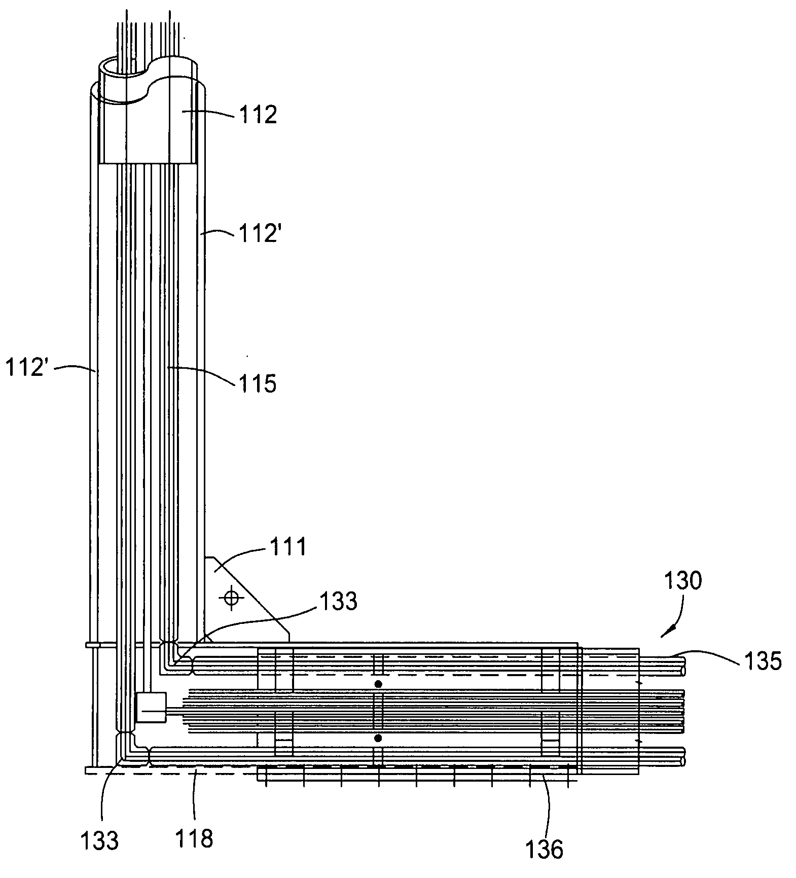
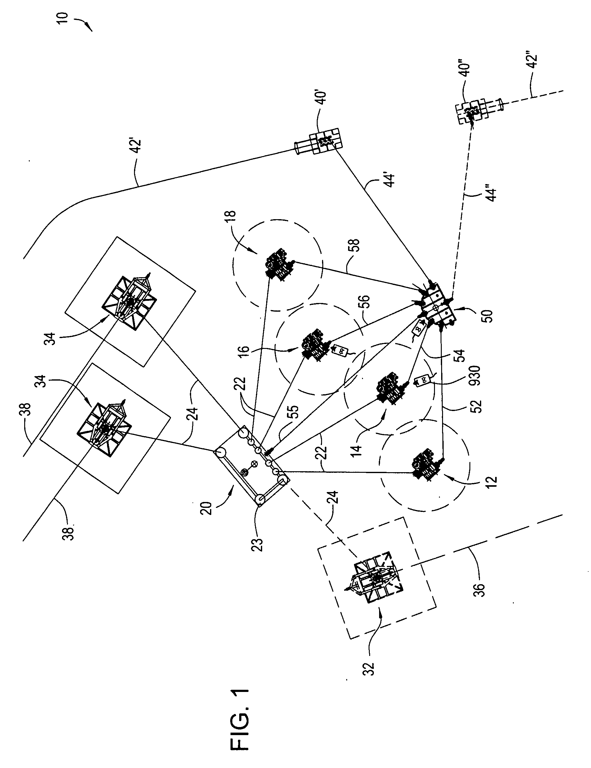
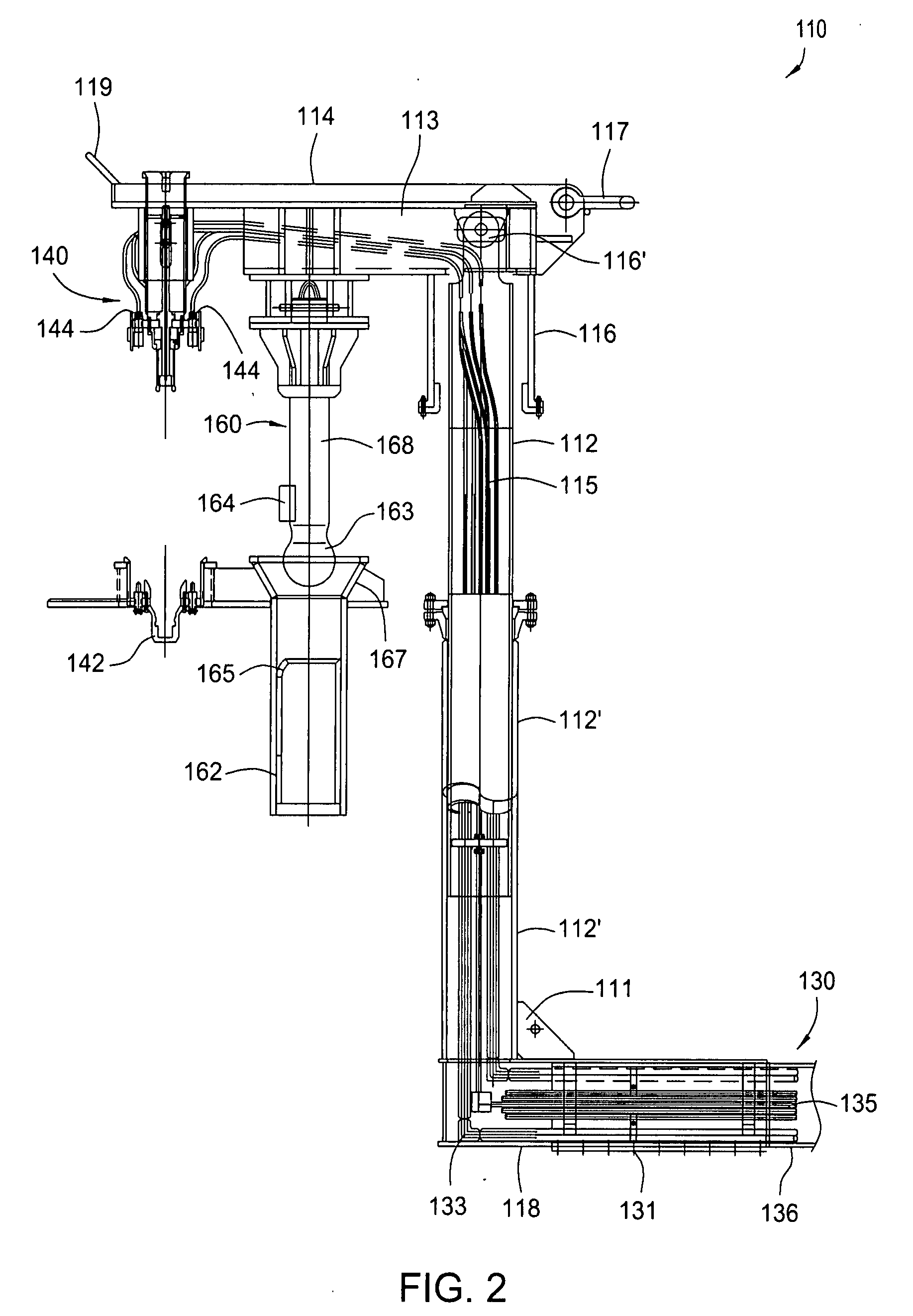
[0038] A flying lead is provided herein. The flying lead enables fluid communication between a first item of subsea equipment and a second item of subsea equipment in a marine body. The flying lead generally includes a first substantially rigid end kit disposed at a first end of the flying lead; a second substantially rigid end kit disposed at a second end of the flying lead; and a substantially rigid and substantially linear midsection. The midsection conveys two or more fluid communication lines between the first end kit and the second end kit. In addition, each of the first and second end kits is configured to be landed into a respective first and second item of subsea equipment by lowering the flying lead into the marine body with a spreader bar.

[0039] Preferably, each of the first and second end kits of the flying lead has an end kit connector for r...


PUM


Abstract

The present invention generally provides a rigid flying lead. The improved flying lead arrangement is configured to provide fluid communication between a first item of subsea equipment and a second item of subsea equipment in a marine body. In one embodiment, the flying lead includes a first substantially rigid end kit disposed at a first end of the flying lead, and a second substantially rigid end kit disposed at a second end of the flying lead. A substantially rigid midsection is defined between the first end kit and the second end kit. At least one, and preferably multiple, fluid communication lines are disposed within the midsection, providing fluid communication between the two items of subsea equipment. Examples of subsea equipment include an umbilical end termination, a subsea distribution unit, a subsea tree and a manifold. The flying lead is configured to be lowered into a marine body using a spreader bar so that junction plates on the respective end kits can be gravitationally landed into respective junction plate receptacles.

Description

CROSS REFERENCE TO RELATED APPLICATIONS [0001] This application claims the benefit of U.S. Provisional Application 60 / 571,276, filed 14 May, 2004.BACKGROUND [0002] 1. Field of the Invention [0003] Embodiments of the present invention generally relate to subsea connections. Such connections may include subsea tie-in monitoring lines, control lines and chemical injection lines. Embodiments of the present invention further pertain to methods for making subsea connections using flying lead connectors. [0004] 2. Description of Related Art [0005] Over the last thirty years, the search for oil and gas offshore has moved into progressively deeper waters. Wells are now commonly drilled at depths of several hundred feet and even several thousand feet below the surface of the ocean. In addition, wells are now being drilled in more remote offshore locations. [0006] The drilling and maintenance of deep and remote offshore wells is expensive. In an effort to reduce drilling and maintenance expens...

Claims


Application Information

Patent Timeline
Patent Type & Authority Applications(United States)
IPC IPC(8): E21B41/04E21B33/038E21B43/013
CPCE21B33/038E21B43/013E21B41/04
Inventor FONTENETTE, LIONEL M.LUGO, MARIO R.
Owner FONTENETTE LIONEL M
Why Eureka
Try Eureka