Eureka AIR delivers breakthrough ideas for toughest innovation challenges, trusted by R&D personnel around the world.

Position detecting device and computer including the same

Active Publication Date: 2007-10-04
WACOM CO LTD
View PDF10 Cites 96 Cited by
  • Summary
  • Abstract
  • Description
  • Claims
  • Application Information

AI Technical Summary

Benefits of technology

[0008] A power supply unit of a position pointer may be configured to be a rechargeable power supply unit such as an electric double-layer capacitor. As a result, an inconvenience associated with exchanging batteries is prevented.

Problems solved by technology

However, even when the rechargeable power supply unit is used, the position pointer must typically be inserted into a separate charging device to charge the power supply unit of the position pointer.
Here, the fact that a user must charge the position pointer in the charging device may result in an inconvenience.
However, when the position detecting device is provided on the rear side of the display device, noise generated by a drive circuit (or other components) in the display device may interfere with the position detection operation.

Method used


Image

  • Position detecting device and computer including the same
  • Position detecting device and computer including the same
  • Position detecting device and computer including the same

Examples


Embodiment Construction

[0048] Reference will now be made in detail to the embodiments of the present invention, examples of which are illustrated in the accompanying drawings, wherein like reference numerals refer to the like elements throughout. The embodiments are described below in order to explain the present invention by referring to the figures.

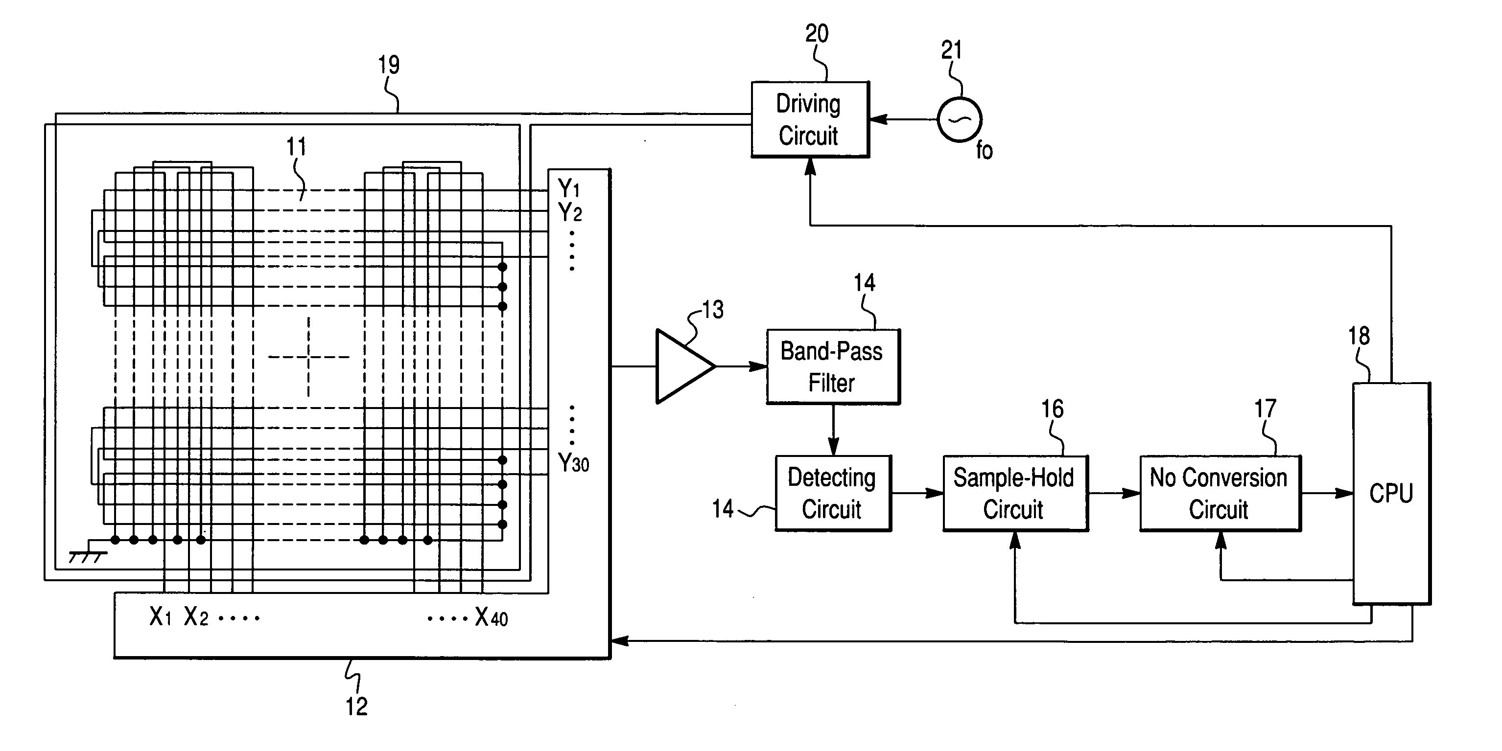
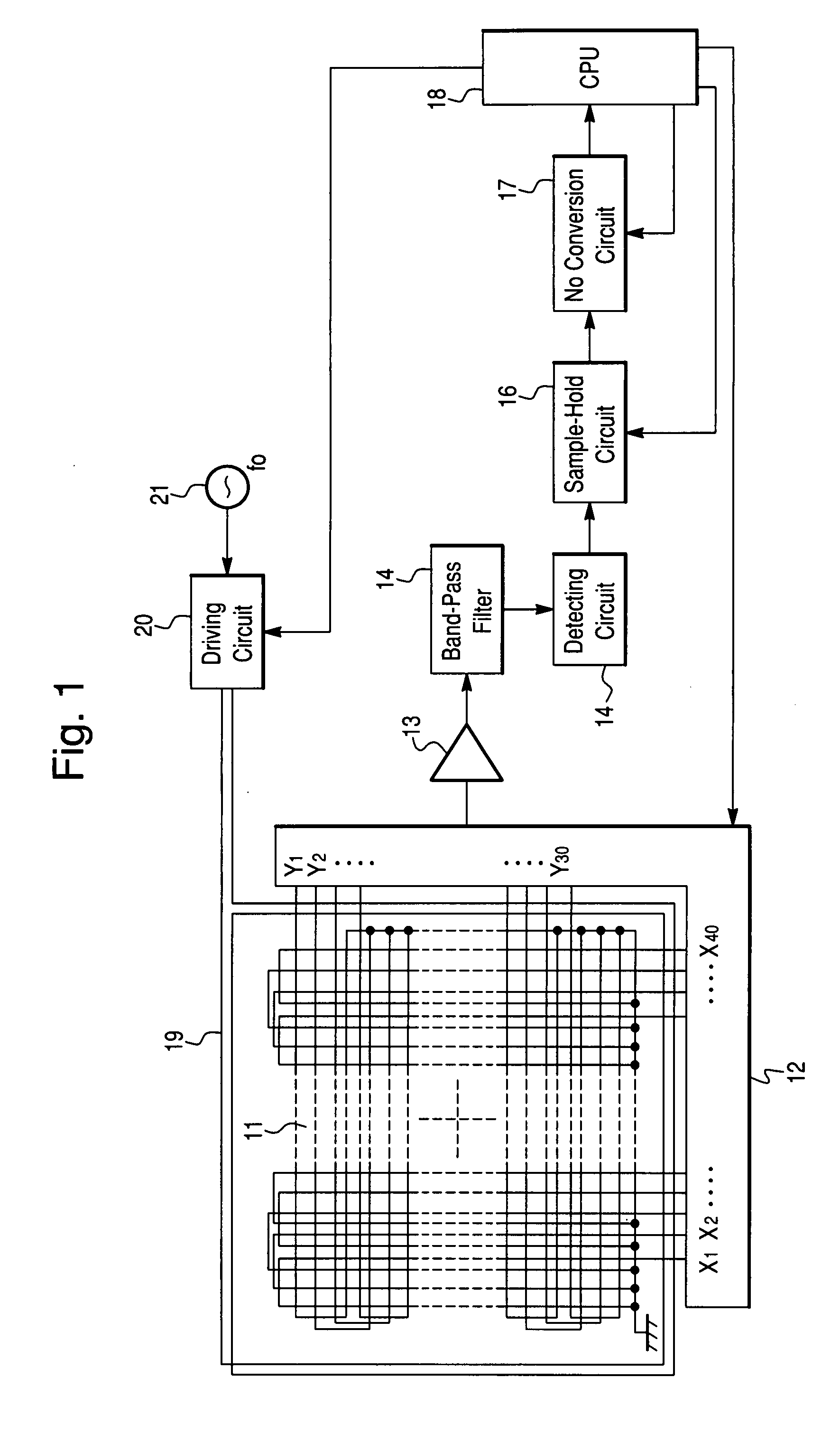
[0049]FIG. 1 is a block diagram including a schematic view illustrating a tablet associated with a position detecting device and computer according to an embodiment of the present invention.

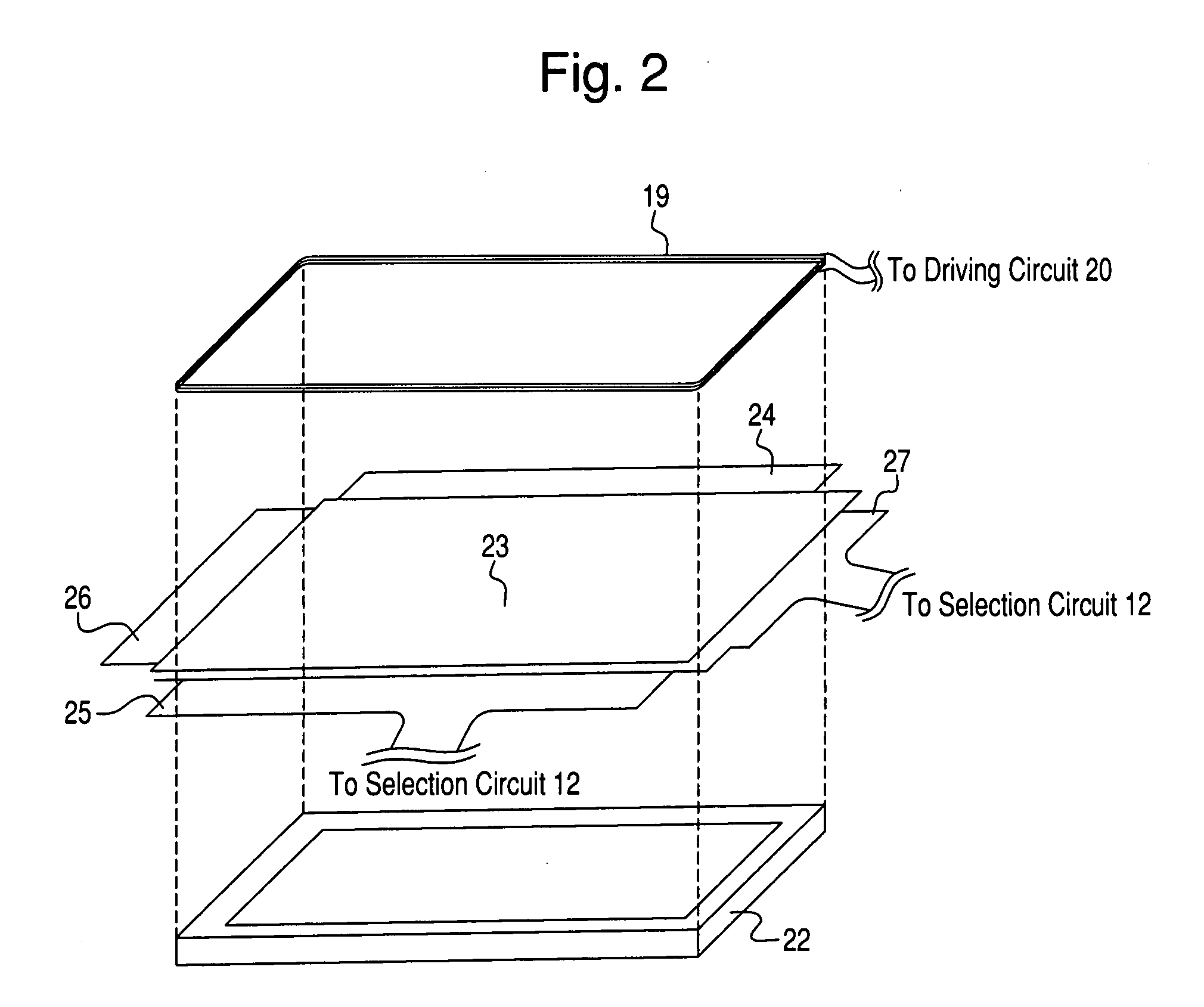
[0050]FIG. 1 illustrates a loop-coil group 11 in which loop coils X1 to X40 and loop coils Y1 to Y30 are arranged along X-axis and Y-axis directions, respectively. A position detecting area configured with the loop-coil group 11 may be integrally formed with an LCD (Liquid Crystal Display) device (not shown in FIG. 1). A size and pitch of the loop-coil group 11 is determined such that the position detecting area corresponds to a display area of the LCD device. Further, t...


PUM


Abstract

A position detecting device is provided. The position detecting device includes a position pointer which transmits a position-pointing signal using a power supply stored in a rechargeable power storage unit, and a tablet which detects a position pointed to by the position pointer when receiving the position-pointing signal. The position pointer includes a coil, a charging circuit for charging the power storage unit, and a transmitter for transmitting the position-pointing signal. The tablet includes an excitation coil wound around a periphery of a position detecting area of the tablet, an excitation circuit for supplying an alternating voltage to the excitation coil, a position-pointing signal detector for detecting the position-pointing signal received from the position pointer, and an excitation controller for controlling a supply of the alternating voltage to the excitation coil based on the detected position-pointing signal.

Description

CROSS REFERENCES TO RELATED APPLICATIONS [0001] The present application claims priority from Japanese Application No. P2006-081605 filed on Mar. 23, 2006, the entire contents of which are incorporated herein by reference. FIELD OF THE INVENTION [0002] The present invention relates to a position detecting device for detecting a position pointed to by a position pointer and a computer including the same. Particularly, when a rechargeable power storage unit is provided in the position pointer, the charge thereof can be easily recharged and conserved. BACKGROUND OF THE INVENTION [0003] Japanese Examined Patent Application Publication No. 02-53805 describes a position detecting device in which a reflective signal is transmitted by a position pointer in sync with a signal transmitted from a tablet where a loop coil is provided. The reflective signal is received by the loop coil in the tablet to detect a position. [0004] Additionally, Japanese Published Patent Application No. 10-214148 des...

Claims


Application Information

Patent Timeline
IPC IPC(8): G06F3/046
CPCG06F3/046G06F1/32
Inventor KATSURAHIRA, YUJI
Owner WACOM CO LTD
Why Eureka
Eureka Blog
Learn More