Thermostat

a technology of thermostats and thermostats, applied in the field of improved thermostats, can solve the problems of wireless communication, inability to achieve the effect of increasing power,

Inactive Publication Date: 2007-10-04
PRO1 IAQ
View PDF3 Cites 345 Cited by
  • Summary
  • Abstract
  • Description
  • Claims
  • Application Information

AI Technical Summary

Benefits of technology

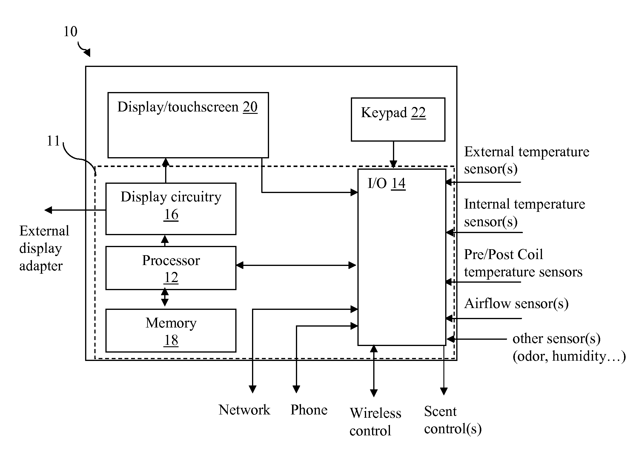
[0015]In the present invention, a thermostat comprises processing circuitry, a housing for mounting on an AC power source, a...

Problems solved by technology

Second, the thermostat can perform functions requiring increased power, such as processor intensive funct...

Method used


Image

  • Thermostat
  • Thermostat
  • Thermostat

Examples


first embodiment

[0064]FIG. 12 illustrates a household HVAC system using the devices of FIGS. 9-11. In the illustrated embodiment, a light switch thermostat 100 and a sensor 110 are positioned in desirable locations on the second floor of a house. A power outlet thermostat 90 and sensor 112 are located on the first floor. Each thermostat or sensor communicates with a wireless receiver 120 (wireless receiver 120 could also be configured to transmit information to the thermostats 90 and 100). Receiver 120 sends information to the controller 84 responsive to information received from the thermostats 90 and 100 and the sensors 110 and 112. Controller 84 then controls the components of the HVAC system.

second embodiment

[0065]FIG. 13 illustrates a household HVAC system using the devices of FIGS. 9-11. In this embodiment, as in FIG. 12, a light switch thermostat 100 and a sensor 110 are positioned in desirable locations on the second floor of a house. A power outlet thermostat 90 and sensor 112 are located on the first floor. In FIG. 13, however, each thermostat or sensor communicates with a thermostat 130 (thermostat 130 could also be configured to transmit information to the thermostats 90 and 100). Thermostat 130 may be battery powered, or coupled to a common connection, and sends information to the controller 84 responsive to information received from the thermostats 90 and 100 and the sensors 110 and 112, along with information that it may detect itself. Controller 84 then controls the components of the HVAC system.

[0066]The embodiment show in FIGS. 9-13 provides significant advantages. First, the availability of power supplied directly or indirectly from the household power provides increased ...


PUM


Abstract

An thermostat 10 includes an improved user interface, including automatic scheduling, remote control, system failure warning messages, and Energy Star compliance messages. Diagnostics can be provided without additional communication links to the thermostat. A sub-base accepts multiple thermostats and uses color coded terminals to ease installation. Glow-in-the-dark features reduce power needs. In one embodiment, thermostats are coupled to AC power sources and communicate using wireless communications to control an HVAC system. A dampered system can be effected through a thermostat that communicates directly with zoned dampers.

Description

CROSS-REFERENCE TO RELATED APPLICATIONS[0001]This application claims the benefit of the filing date of copending provisional application U.S. Ser. No. 60 / 786,635, filed Mar. 28, 2006, U.S. Ser. No. 60 / 746,730 filed May 8, 2006, U.S. Ser. No. 60 / 825,800 filed Sep. 15, 2006 and U.S. Ser. No. 60 / 827,204 filed Sep. 27, 2006, which are incorporated by reference herein.STATEMENT OF FEDERALLY SPONSORED RESEARCH OR DEVELOPMENT[0002]Not ApplicableBACKGROUND OF THE INVENTION[0003]1. Technical Field[0004]This invention relates in general to heating and air conditioning systems and, more particularly, to an improved thermostat for a heating and air conditioning system.[0005]2. Description of the Related Art[0006]A home's air conditioning system, which could include a heating furnace and / or a cooling coil, is one of the most important appliances in a home or business setting. Not only is the air conditioning system one of the most expensive appliances in a home or business, the proper operation ...

Claims


Application Information

Patent Timeline
IPC IPC(8): G05D23/12B64D13/00
CPCF24F11/0012F24F11/0086G05D23/1905F24F2011/0072Y02B60/50F24F2011/0067F24F11/30F24F11/54F24F11/59F24F2110/10F24F11/52F24F11/39F24F11/36F24F11/46F24F11/63F24F11/38F24F11/56
Inventor KENNEDY, KIMBERLY A.EDGAR, JEFFREY
Owner PRO1 IAQ
Why Eureka
Try Eureka