
Stable electro-mechanical actuators

a technology of electro-mechanical actuators and actuators, which is applied in the direction of mirrors, instruments, mountings, etc., can solve the problems of limited mechanical operation of electro-mechanical actuators, and achieve the effect of increasing the rang

Inactive Publication Date: 2007-10-04
ALCATEL-LUCENT USA INC
View PDF8 Cites 26 Cited by
  • Summary
  • Abstract
  • Description
  • Claims
  • Application Information

AI Technical Summary

Benefits of technology

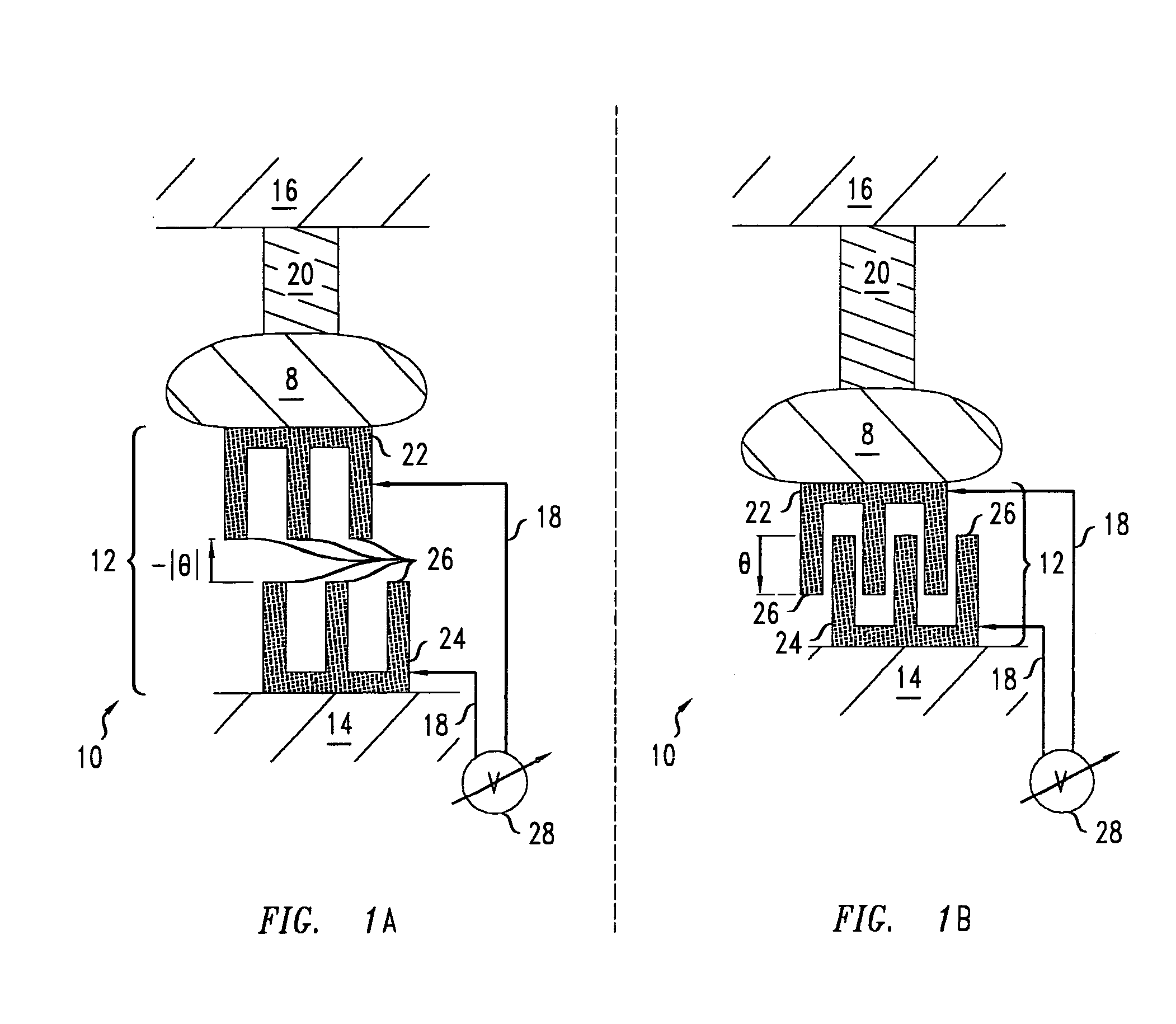
[0009] Various embodiments provide electro-mechanical actuators that are based on comb drives. Some such electro-mechanical actuators provide a limited mechanical operation range over which the teeth of each comb drive therein are inter-digitated. For that reason, it may be advantageous to have electro-mechanical actuators configured to enable the teeth of one or more comb drive to disengage. Some embodiments of the electro-mechanical actuators are configured so that teeth of one or more comb drive therein can disengage over a portion of the actuator's mechanical operation range. Some such mechanical actuators may provide increased ranges for produced displacements and / or orientations due to the absence of a requirement that the teeth of each comb drive be engaged over the entire range of mechanical operation of the actuators.

Problems solved by technology

Some such electro-mechanical actuators provide a limited mechanical operation range over which the teeth of each comb drive therein are inter-digitated.

Method used


Image

  • Stable electro-mechanical actuators
  • Stable electro-mechanical actuators
  • Stable electro-mechanical actuators

Examples


Embodiment Construction

[0037] The various embodiments include electro-mechanical actuators that have one or more comb drives. Some structures for electro-mechanical actuators and comb drives and / or methods of fabricating such structures may be described in U.S. patent application Ser. No. 10 / 813,951 filed on Mar. 31, 2004 by Vladimir A. Aksyuk et al and in U.S. patent application Ser. No. 11 / 140,313 filed on May 27, 2005 by Vladimir A. Aksyuk. These patent applications are incorporated herein by reference in their entirety.

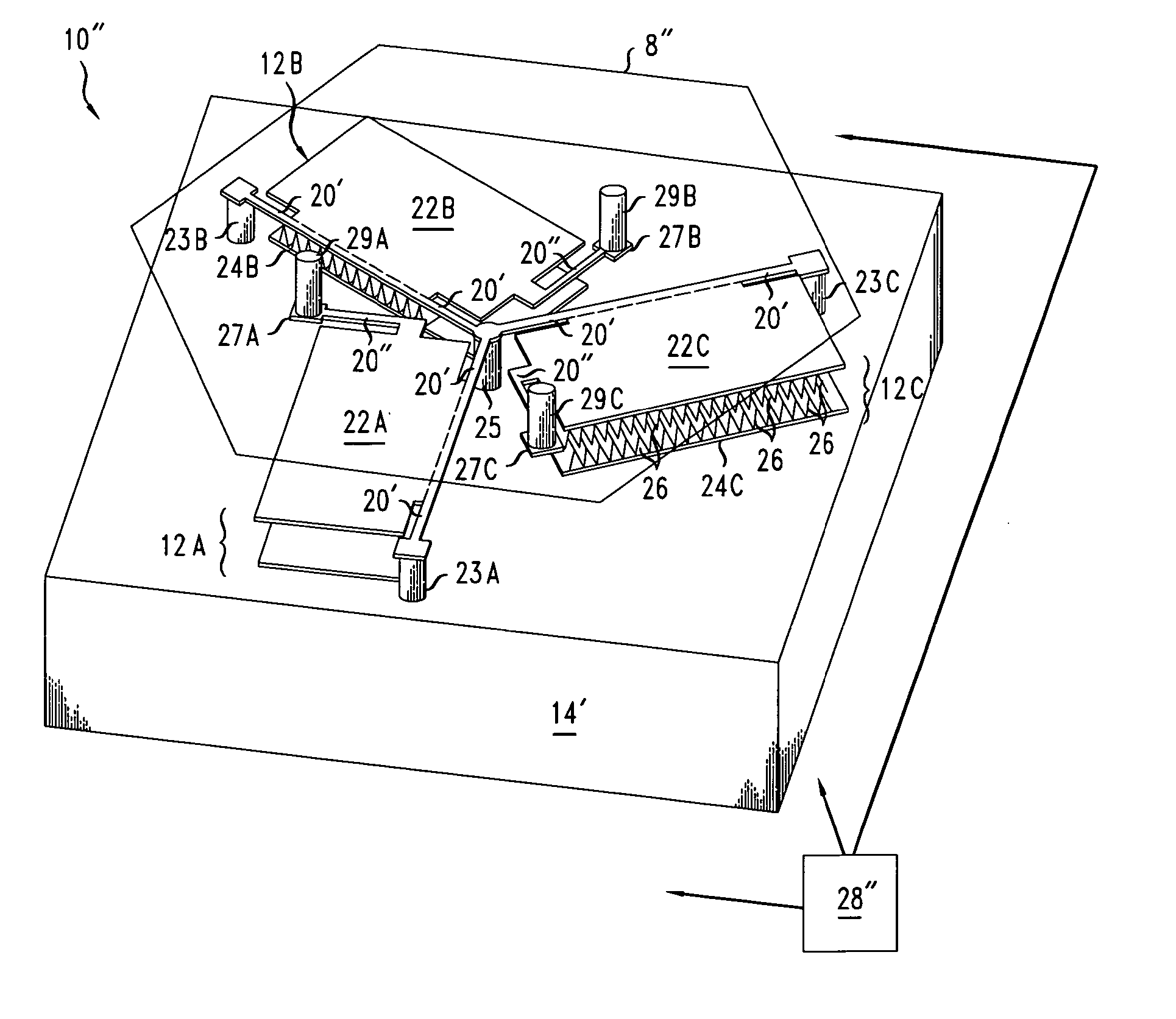
[0038] Herein, some embodiments of the electro-mechanical actuators are, e.g., micro-electro-mechanical systems (MEMS). MEMS are electro-mechanical devices that have some functional features with dimensions of less than about 10 micrometers. Some of the electro-mechanical actuators 10, 10′, 10″, 10′″ of of FIGS. 1A, 1B, 7, and / or 8A-8B may have comb drives with teeth 26 whose widths are less than about 4 micrometers or even less than about 0.5 micrometers. Similarly, some of the electr...


PUM


Abstract

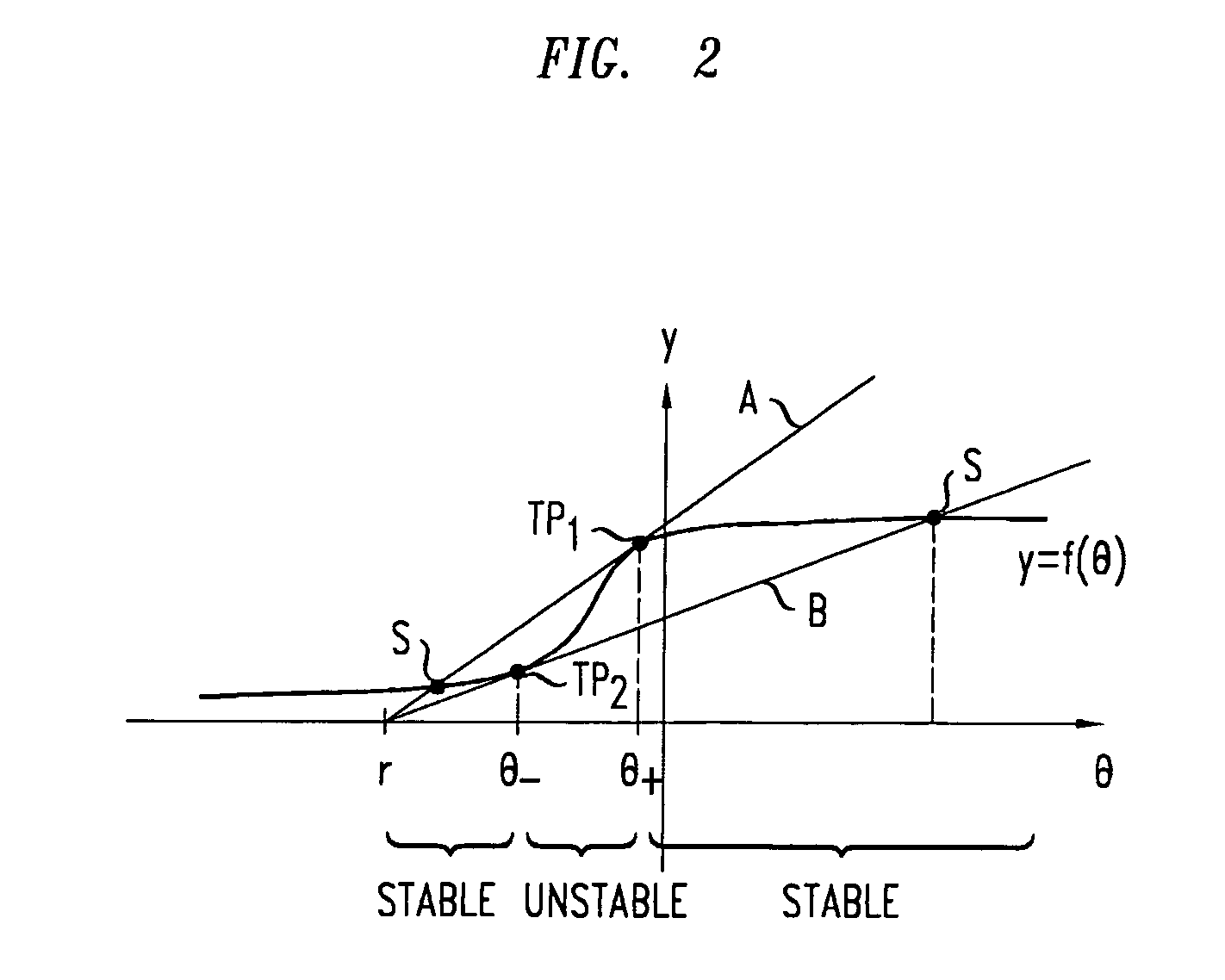
An electro-mechanical actuator includes a comb drive and a deformable connector. The comb drive has a first capacitor plate and a second capacitor plate. The capacitor plates have teeth capable of inter-digitating. The deformable connector is configured to apply a mechanical restoring force to the first capacitor plate. The deformable connector is configured to restore the first capacitor plate to be at an equilibrium rest position in response to no control voltage being applied across the capacitor. The comb drive is more engaged at the equilibrium rest position than at a mechanical stability threshold of the comb drive. The capacitor plates are disengaged at the equilibrium rest position.

Description

[0001] The U.S. Government has a paid-up license in this invention and the right in limited circumstances to require the patent owner to license others on reasonable terms as provided for by the terms of contract No. HR0011-04-C-0048 awarded by DARPA under CCIT.BACKGROUND [0002] 1. Technical Field [0003] The invention relates to electro-mechanical actuators, methods of calibrating electro-mechanical actuators, and method of operating electro-mechanical actuators. [0004] 2. Discussion of Related Art [0005] This section introduces aspects that may facilitate a better understanding of the invention. Accordingly, the statements of this section are to be read in that light. The statements of this section are not admissions about what is in the prior art or about what is not in the prior art. [0006] Many electro-mechanical actuators incorporate a comb drive. Herein, a comb drive refers to a capacitor having two capacitor plates, wherein each capacitor plate has teeth capable of inter-digi...

Claims


Application Information

Patent Timeline
IPC IPC(8): G02B26/08H02N1/00G02B7/182
CPCG02B7/1827H02N1/008G02B26/0841
Inventor AKSYUK, VLADIMIR ANATOLYEVICHNUZMAN, CARL JEREMYSIMON, MARIA ELINAWEISS, ALAN
Owner ALCATEL-LUCENT USA INC
Learn More