Piezoelectric Sounding Body

a sounding body and piezoelectric technology, applied in piezoelectric/electrostrictive/magnetostrictive devices, piezoelectric/electrostriction/magnetostriction machines, instruments, etc., can solve the problems of high resonance frequency, pressure drop sharply, and substantially flat sound pressure characteristic cannot be obtained over a wide band, so as to reduce the number of components and simplify the attaching process. , the effect of low cos

Active Publication Date: 2007-10-04
MURATA MFG CO LTD
View PDF7 Cites 27 Cited by
  • Summary
  • Abstract
  • Description
  • Claims
  • Application Information

AI Technical Summary

Benefits of technology

[0015] According to the preferred embodiment, the piezoelectric sounding body may have the following structure. That is to say, the case includes a front case and a rear case. The front case and the rear case are each an integral metal component having a central portion having sound emitting holes. The front case and the rear case are drawn so that their central portion are away from the tackiness layer of the resin film in the thickness direction. Peripheral flanges of the front case and the rear case are attached to both surfaces of the resin film. In this case, the flange of the front case can be attached using the tackiness layer formed on the one surface of the resin film. Therefore, the attaching process can be simplified, and the number of components constituting the case can be reduced. Therefore, a thin and low-cost piezoelectric sounding body can be achieved. Incidentally, the rear case can be attached to the lower surface of the resin film using an adhesive or a pressure-sensitive agent.
[0016] According to the preferred embodiment, a terminal plate may be attached to a part of the periphery of the one surface of the resin film with the tackiness layer. An electrode on the surface of the piezoelectric vibrating plate and an electrode on the surface of the terminal plate may be electrically connected via a lead. A front case having sound emitting holes and covering the piezoelectric vibrating plate without being in contact therewith may be attached with the tackiness layer to the periphery of the one surface of the resin film except for the region to which the terminal plate is attached. A rear case having sound emitting holes and covering the central portion of the resin film without being in contact therewith may be attached to the periphery of the other surface of the resin film. A lead for external connection may be directly connected to the piezoelectric vibrating plate. However, in this case, the load exerted on the lead acts directly on the piezoelectric vibrating plate and hinders the vibration of the piezoelectric vibrating plate. In addition, if a large tensile force acts on the lead, the piezoelectric vibrating plate can be damaged. When a terminal plate is attached to the resin film and the terminal plate and the piezoelectric vibrating plate are connected via a lead, external connection is performed via the terminal plate. Therefore, an external load can be prevented from acting directly on the piezoelectric vibrating plate, and a signal can be easily input into the piezoelectric vibrating plate. Although the terminal plate can be attached to any place on the periphery of the resin film, the terminal plate is preferably attached to a place along one short side of the piezoelectric vibrating plate. The reason is that the amount of displacement of the film during sounding is relatively small.
[0017] According to the preferred embodiment, it is preferable that the lead be a metal wire, both ends of the lead be connected to the electrode on the surface of the piezoelectric vibrating plate and the electrode on the surface of the terminal plate, and a slack be formed in the middle of the lead. In this case, since the lead has a slack in the middle thereof, the relative displacement between the piezoelectric vibrating plate and the terminal plate can be permitted. Therefore, the piezoelectric vibrating plate can vibrate smoothly, and an excellent sound pressure characteristic can be obtained.
[0018] As described above, according to the present invention, a rectangular piezoelectric vibrating plate is attached to a resin film, and the periphery of the film is supported by a case. Therefore, the vibrating plate can have resonance frequencies in odd order resonance modes, for example, a fundamental harmonic wave, a third order harmonic wave, and a fifth order harmonic wave, according to the lengths of the short side and the long side, independently. By an optimum resonance mode arrangement, a flat sound pressure characteristic can be obtained over a wide band. In addition, since the piezoelectric vibrating plate is attached on a tackiness layer formed on the resin film, a uniform film thickness of the tackiness layer between the resin film and the piezoelectric vibrating plate can be provided. In addition, the tackiness agent does neither creep up onto the piezoelectric vibrating plate nor seep close to the edge of the film. In addition, since a thermosetting process is not necessary unlike the case where an adhesive is used, the resin film has no heat history, and therefore deterioration can be prevented. In addition, an adhesive is applied between the middle of each long side of the piezoelectric vibrating plate and the resin film, along each long side of the piezoelectric vibrating plate. Therefore, a separation does not occur at the interface between the middle of each long side of the piezoelectric vibrating plate and the tackiness layer of the resin film during sounding, and a stable sound pressure can be obtained for a prolonged period.

Problems solved by technology

Therefore, conventional piezoelectric sounding bodies have the problem of high resonance frequency.
In addition, the sound pressure drops sharply between the primary resonance frequency and the secondary resonance frequency, and a substantially flat sound pressure characteristic cannot be obtained over a wide band.
However, if the resonance frequencies exist apart from each other, or if one of the odd order resonance modes is extremely excited, a large peak and trough occur in the sound pressure frequency characteristic and cause a deterioration in sound quality.
However, in the case where a thermosetting adhesive is used, the viscosity of the adhesive decreases temporarily during thermosetting.
For example, if a soldering electrode is contaminated with the adhesive, a poor connection can occur.
In addition, the adhesive can seep close to the edge of the film and become a hindrance when a case or the like is attached to the film.
In addition, it is difficult to make the film thickness of the adhesive between the resin film and the piezoelectric vibrating plate uniform.
In addition, since the resin film is heated in each setting process, the resin film tends to deteriorate.
The reason is that, in the case of a rectangular piezoelectric vibrating plate, displacement in the middle in the longitudinal direction thereof is largest, and the tackiness layer does not have an adhesive force sufficient to follow the displacement of the piezoelectric vibrating plate.
Once a separation occurs, the driving force of the piezoelectric vibrating plate is not sufficiently transmitted to the resin film, and therefore a drop in sound pressure occurs.

Method used


Image

  • Piezoelectric Sounding Body
  • Piezoelectric Sounding Body
  • Piezoelectric Sounding Body

Examples


example 1

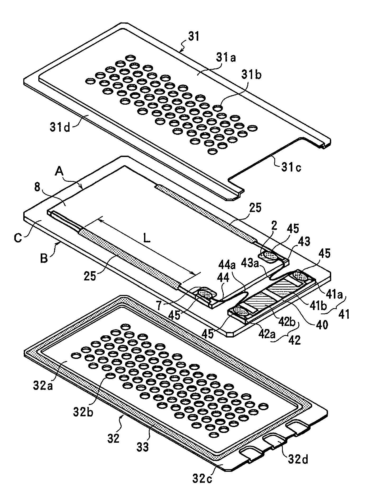
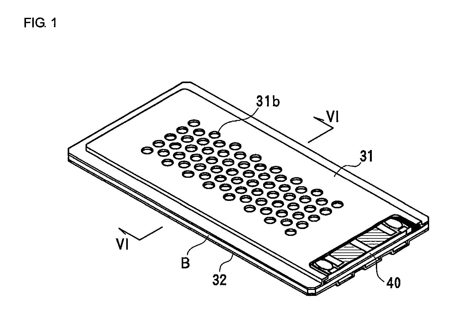
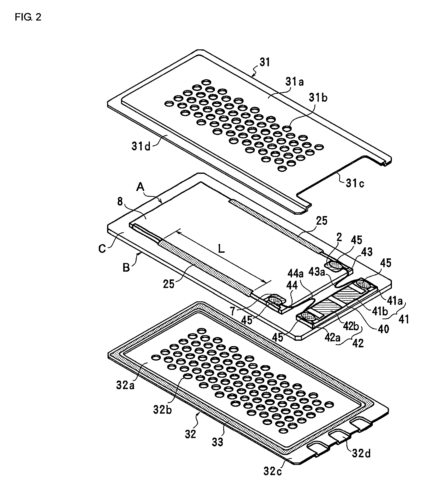
[0048] FIGS. 1 to 6 show an example of a piezoelectric speaker, which is a first example of a piezoelectric sounding body according to the present invention. This example has a rectangular piezoelectric vibrating plate A and a rectangular resin film B to which the piezoelectric vibrating plate A is attached, and a case containing the resin film B. The case includes a front case 31 having many sound emitting holes 31b, and a rear case 32 having many sound emitting holes 32b.

[0049] As shown in FIGS. 4 and 5, the piezoelectric vibrating plate A includes two laminated piezoelectric elements 1 and 10 with an intermediate layer 20 interposed therebetween, and has a general shape of a rectangular plate. The upper piezoelectric element 1 has two laminated piezoelectric ceramics layers 1a and 1b. Main surface electrodes 2 and 3 are formed on the upper and lower main surfaces of the piezoelectric element 1. An internal electrode 4 is formed between the ceramics layers 1a and 1b. The two cera...

example 2

[0062]FIG. 9 shows a second example of a piezoelectric sounding body. The same reference numerals will be used to designate the same components as those in the first example, so that the description will be omitted. The piezoelectric sounding body of this example differs from the first example in the structure of the case supporting the periphery of the resin film B. The periphery of the resin film B to which the piezoelectric vibrating plate A has been attached is sandwiched and supported from above and below by frames 34 and 35, the frames 34 and 35 being attached to the resin film B. Next, flat covers 36 and 37 having sound emitting holes 36a and 37a are attached to the frames 34 and 35. Thus, a case is constructed. The upper frame 34 is formed in a square U-shape open toward the terminal plate 40. The lower frame 35 is formed in a hollow square. The adhesive 33 bonding the frame 35 and the resin film B is formed in the same shape as the frame 35. Also in this case, a tackiness l...


PUM


Abstract

A piezoelectric sounding body in which a stable high sound pressure can be obtained over a wide frequency band. The piezoelectric sounding body includes a resin film, a piezoelectric vibrating plate attached to the center of one surface of the resin film with a tackiness layer, and a case supporting the periphery of the resin film. The piezoelectric vibrating plate is formed in a rectangular shape. An adhesive is applied between the middle of each long side of the piezoelectric vibrating plate and the resin film, along each long side of the piezoelectric vibrating plate. The separation between the piezoelectric vibrating plate and the tackiness layer can be prevented during sounding, and a stable sound pressure can be obtained for a prolonged period.

Description

CROSS REFERENCE TO RELATED APPLICATIONS [0001] The present application is a continuation of International Application No. PCT / JP2006 / 322621, filed Nov. 14, 2006, which claims priority to Japanese Patent Application No. JP2006-043402, filed Feb. 21, 2006, the entire contents of each of these applications being incorporated herein by reference in their entirety.FIELD OF THE INVENTION [0002] The present invention relates to piezoelectric sounding bodies, for example, piezoelectric speakers and piezoelectric sounders. BACKGROUND OF THE INVENTION [0003] Piezoelectric sounding bodies are widely used as a piezoelectric sounder or a piezoelectric speaker in electronic devices, home electric appliances, cell-phones, and the like. Conventional piezoelectric sounding bodies have a piezoelectric vibrating plate contained in a case. The periphery of the piezoelectric vibrating plate is fixed to the case. Therefore, conventional piezoelectric sounding bodies have the problem of high resonance fre...

Claims


Application Information

Patent Timeline
Patent Type & Authority Applications(United States)
IPC IPC(8): H01L41/00H04R17/00
CPCH04R17/00G10K9/122
Inventor YAMAUCHI, MASAKAZUKUSABIRAKI, SHIGEMASA
Owner MURATA MFG CO LTD
Why Eureka
Try Eureka