
Multipurpose Optical Signalling Device, Particularly for Road Emergency in Low Visibility Conditions

a multi-purpose, optical signaling technology, applied in the direction of visible signalling system, protective device for lighting, lighting and heating apparatus, etc., can solve the problems of excessive diffused lighting, serious accidents risk for road users, and dependence on the effectiveness of retroreflective materials, etc., to achieve simple, safe and timely manner

Inactive Publication Date: 2007-10-04
ASTRON FIAMM SAFETY
View PDF12 Cites 9 Cited by
  • Summary
  • Abstract
  • Description
  • Claims
  • Application Information

AI Technical Summary

Benefits of technology

[0019] The object of this invention is to overcome the above drawbacks, while providing a multi-purpose emergency warning device that is practical, cost-effective and most of all efficient.
[0021] A further object is to provide a signal that is visible from long distances, to allow oncoming drivers to perceive the danger well before reaching the position where the signal has been placed.
[0022] One more object is to provide a device that allows to orient the light beam toward oncoming vehicles, even in extreme conditions, such as in curves.
[0023] Another object is to provide a signal that requires a low power supply, while providing good visibility of the light source, so that no problems occur in case of long stays.
[0024] Furthermore, a particular object of this invention is to provide a signal that, although it is used very near the stopped vehicle, is capable of signaling the vehicle from a suitable distance to prevent the user from dangerously passing beyond the edge of the road.
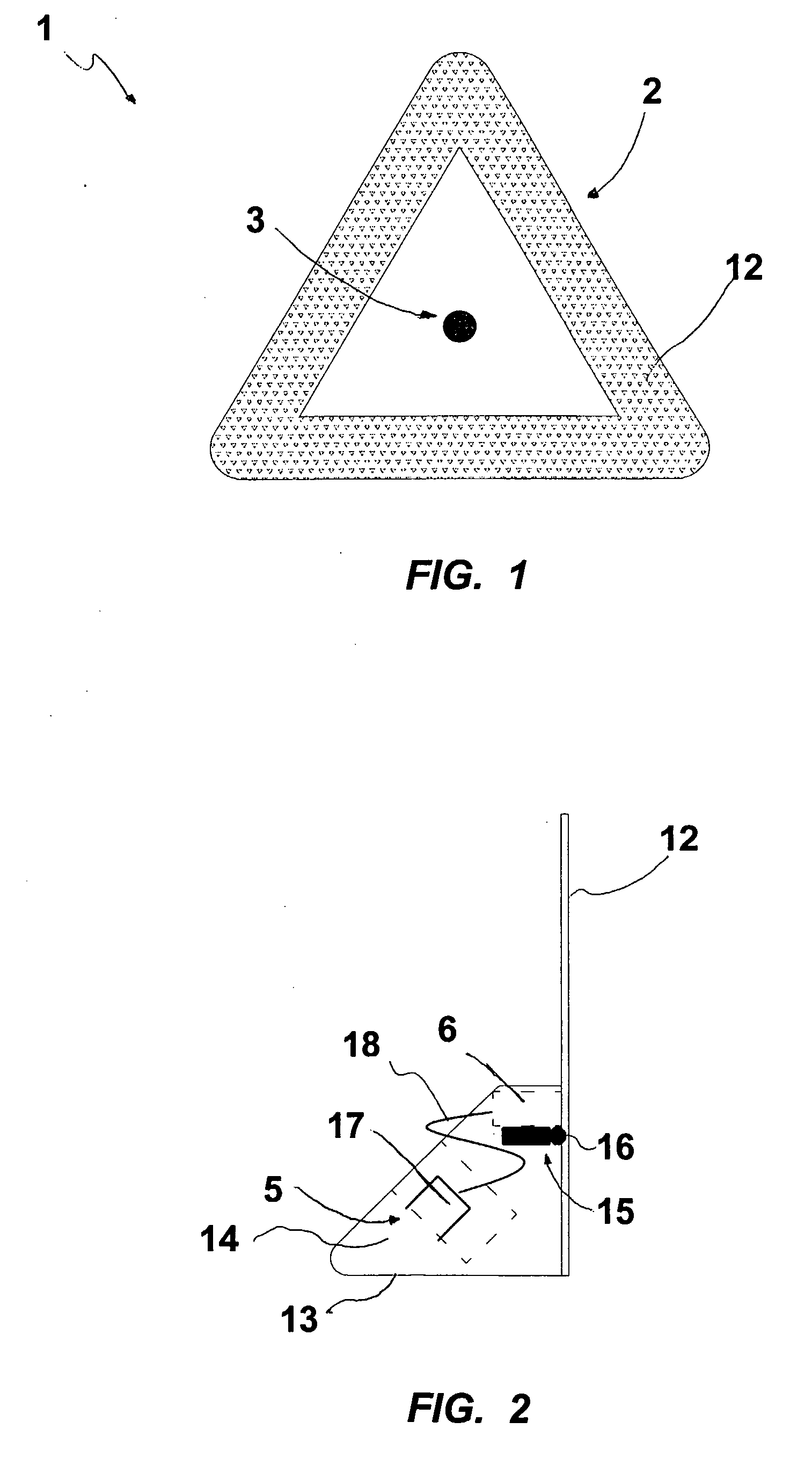
[0031] The support structure may have a front portion that defines a warning triangle, to be attached to the base. By this particular arrangement, the apparatus of the invention allows to signal the danger deriving from an obstacle on the roadway in a simple, safe and timely manner, particularly in low visibility conditions.

Problems solved by technology

In particularly low visibility conditions, these equipments may be insufficient, whereby the road user is exposed to serious risks of accidents.
This prior art arrangement has the drawback that the effectiveness of retroreflective material is dependent on the intensity of the light source that lights it up.
A further advantage of this device is that, in low visibility conditions caused by fog, if the approaching vehicle uses upper beams, the light reflected by the fog causes an excessive diffused lighting which may dazzle the driver.
In addition to the disadvantages as set out above, such prior art device has the drawback that it has to be placed on the vehicle, e.g. on the roof, due to the power supply arrangement, to provide a signal that is eventually untimely, especially in low visibility conditions.
An additional shortcoming of this triangle is that, in case of a long stay, it may discharge the car battery, thereby causing serious damages thereto.
This prior art arrangement has the drawback of dazzling the driver, the light source having a very high intensity.
Furthermore, it has a very complex light control arrangement, which requires a high battery power absorption, whereby batteries tend to discharge rapidly, which makes the device unusable in case of long stays.
These devices are also of little use, especially in low visibility conditions, as they generate a very low-intensity light beam.
Generally, all the above prior art arrangements have the drawback that, to provide an effective emergency warning signal, the user has to place the device at a very short distance from the stopped or disabled vehicle, as prescribed by applicable rules, and is thereby exposed to danger.
However, no attempt has been made heretofore to use a laser light source on a fixed signaling device like a warning triangle.

Method used


Image

  • Multipurpose Optical Signalling Device, Particularly for Road Emergency in Low Visibility Conditions
  • Multipurpose Optical Signalling Device, Particularly for Road Emergency in Low Visibility Conditions
  • Multipurpose Optical Signalling Device, Particularly for Road Emergency in Low Visibility Conditions

Examples


Embodiment Construction

[0037] Referring to the above mentioned figures, the multi-purpose visual device according to the invention, particularly intended for road use in low visibility conditions, is generally denoted by numeral 1.

[0038] The device 1 comprises a support structure 2, which may stand on the ground, with light-emitting means 3 for generating a light beam 4 and means 5 for supplying power to the light-emitting means 3 being removably mounted thereto.

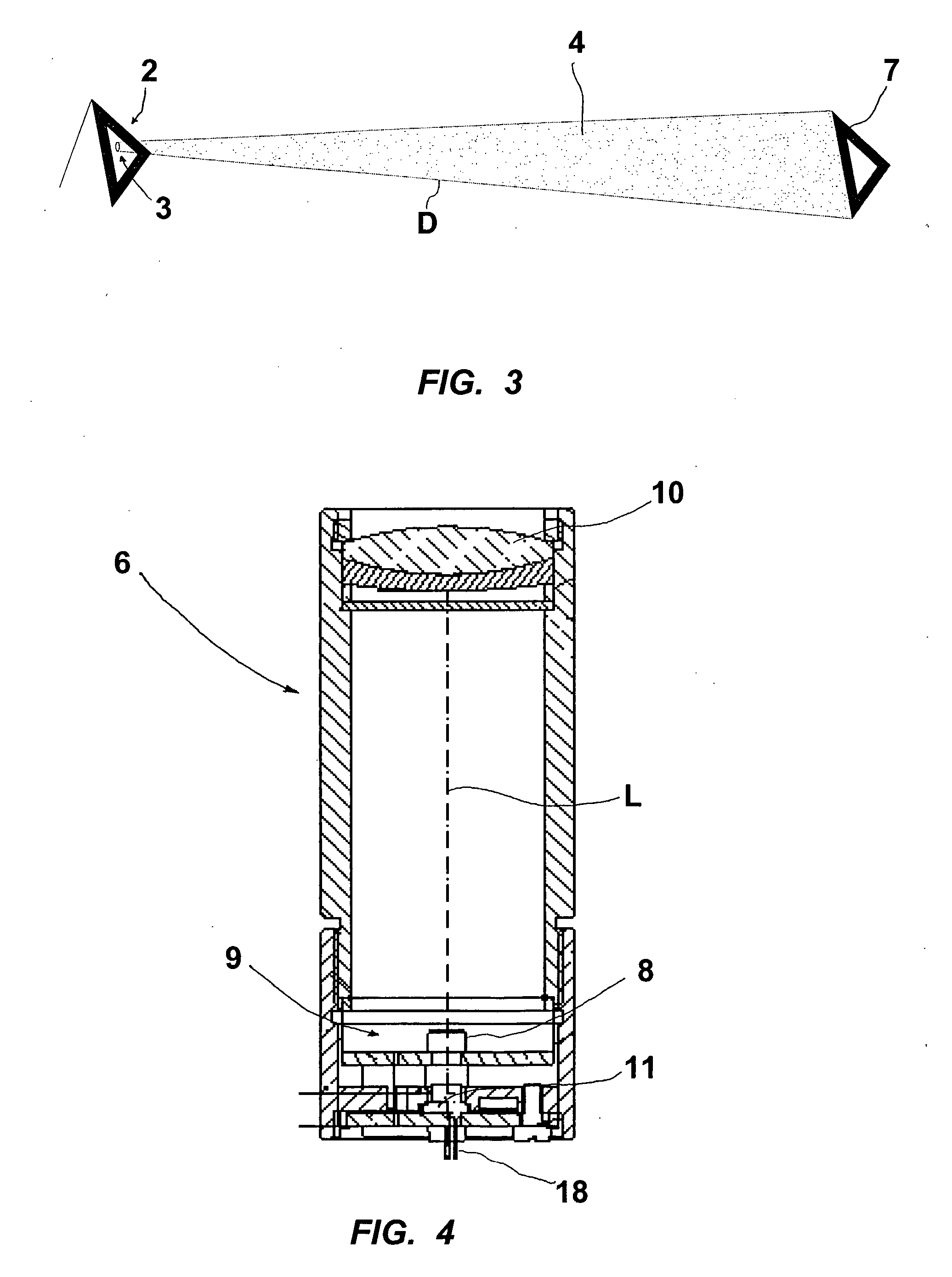
[0039] Particularly, such means include at least one laser projector 6 adapted to project images 7 over a substantially flat surface for such images to be visible from a relatively long distance.

[0040] Conveniently, the laser projector 6 may include a laser diode 8.

[0041] The laser projector 6 may further comprise optical and / or electronic means 9 for generating one or more images 7 in space or over a substantially flat surface, such as the roadway.

[0042] The optical and / or electronic means 9 may be selected among: lenses, prisms, mirrors, LC...


PUM


Abstract

A multi-purpose visual signaling device, particularly for road emergency warning and in low visibility conditions, comprises light-emitting means (3) for generating a light beam (4) and means (5) for supplying power to light-emitting means (3). The light-emitting means (3) include at least one laser projector (6) adapted to project images (7) over a substantially flat surface for such images to be visible from a relatively long distance. The light-emitting means (3) and the power supply means (5) are mounted to a stationary support structure (2) which may include a front warning triangle-defining portion (12). The laser projector (6) comprises at least one laser diode (8) and optical and / or electronic means (9) for generating images (7) in space or over a substantially flat surface. The optical and / or electronic means (9) comprise a diffractive lens (10). Images (7) include monochromatic, polychromatic and / or holographic images, possibly of variable configuration, and preferably form a triangular design.

Description

FIELD OF THE INVENTION [0001] This invention finds application in the field of road safety and particularly relates to a multi-purpose visual signaling device. [0002] More particularly, the invention relates to a visual signaling device for road emergency warning, which may be carried aboard a car or similar vehicle, and may be used to signal the presence of the vehicle or the person carried thereby to prevent accidents, especially in low visibility conditions. BACKGROUND ART [0003] Fixed obstacles on the road, such as tollgates, roadwork sites, accidented vehicles, road maintenance workers, have various devices designed to make them easily visible, especially in the dark or in particular environmental conditions, such as fog, snow or rain. [0004] Currently available equipments essentially consist of active or passive visual devices, such as signaling lights, reflex reflectors, warning triangles. [0005] In particularly low visibility conditions, these equipments may be insufficient,...

Claims


Application Information

Patent Timeline
IPC IPC(8): B60Q7/00B60Q1/52
CPCB60Q2400/50B60Q7/00
Inventor DOLCETTA, ALESSANDROFILOSOFO, ALBERTO
Owner ASTRON FIAMM SAFETY
Learn More