Ink Cartridges And Inkjet Printers

Active Publication Date: 2007-10-04
BROTHER KOGYO KK
View PDF9 Cites 19 Cited by
  • Summary
  • Abstract
  • Description
  • Claims
  • Application Information

AI Technical Summary

Benefits of technology

[0009]According to an embodiment of the present invention, an ink cartridge comprises a wall, and an ink supply portion positioned at the wall. For example, the ink supply portion may extend from the wall or may be substantially flush with the wall, and may be positioned adjacent to an end of the wall. The ink supply portion has an ink supply opening formed therein. The ink cartridge also comprises a plurality of protrusions which comprise a first protrusion and a second protrusion, and each of the first protrusion and the second protrusion extend from the wall. In an embodiment, a distance between the first protrusion and the second protrusion is greater than 0 mm and less than a diameter of the ink supply opening. In another embodiment, the distance between the first protrusion and the second protrusion is greater than 0 mm and less than a diameter of the ink supply opening.
[0010]According to another embodiment of the present invention, an ink cartridge comprises an ink chamber configured to store an ink, and a wall comprising a first end and a second end opposite the first end, and an ink supply portion which is positioned at the wall adjacent to the second end of the wall and protrudes from the wall. The ink supply portion has an end portion and an ink supply opening formed in the end portion, and the ink supply portion is configured to supply the ink from an interior of the ink chamber to an exterior of the ink cartridge through the ink supply opening. The ink cartridge also comprises a plurality of protrusions protruding from the wall, and each of the plurality of protrusions has an end portion. Moreover, a first distance between the end portion of each of the p

Problems solved by technology

When the ink drips from the ink supply opening onto the mounting portion, the mounting portion becomes dirtied.
After the mounting portion becomes dirtied, when a new ink cartridge i

Method used


Image

  • Ink Cartridges And Inkjet Printers
  • Ink Cartridges And Inkjet Printers
  • Ink Cartridges And Inkjet Printers

Examples


Embodiment Construction

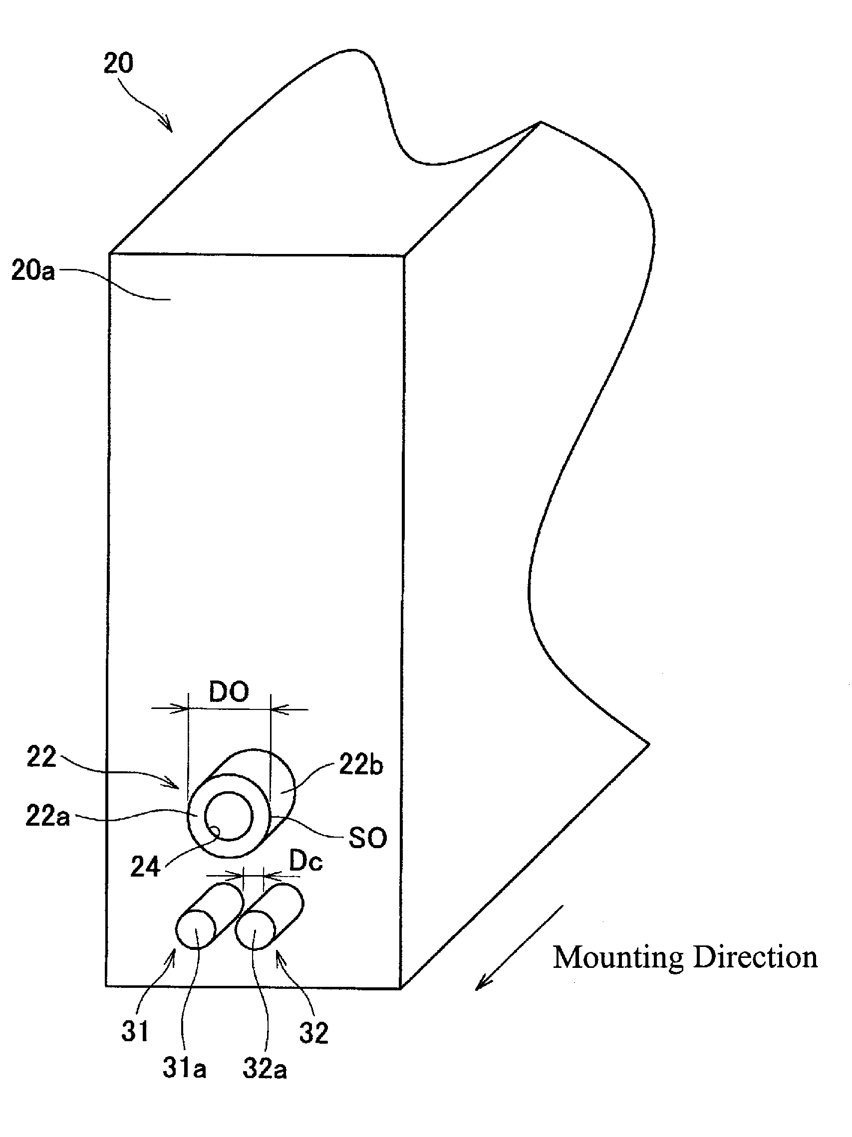
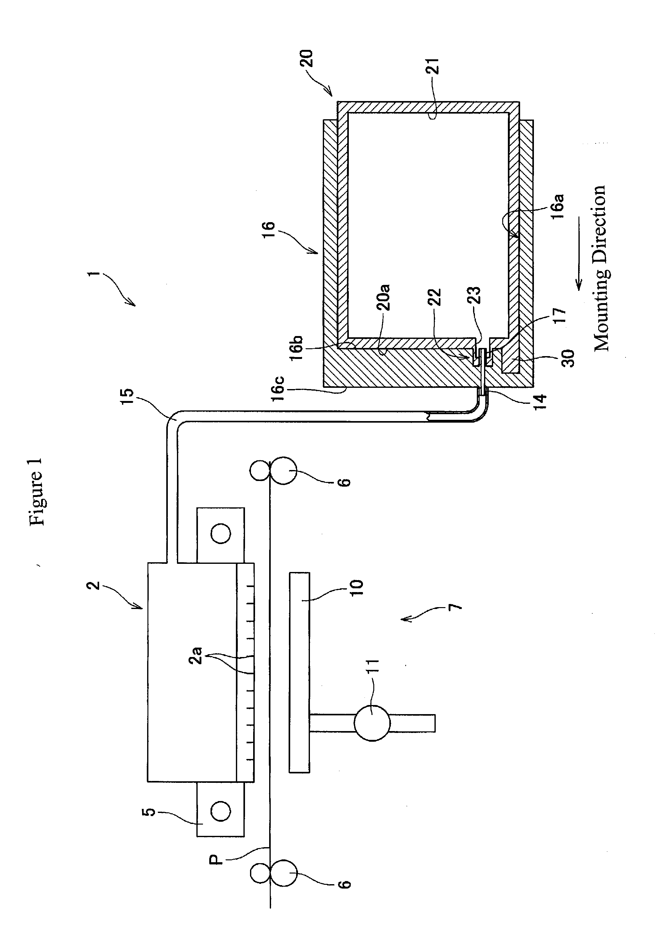
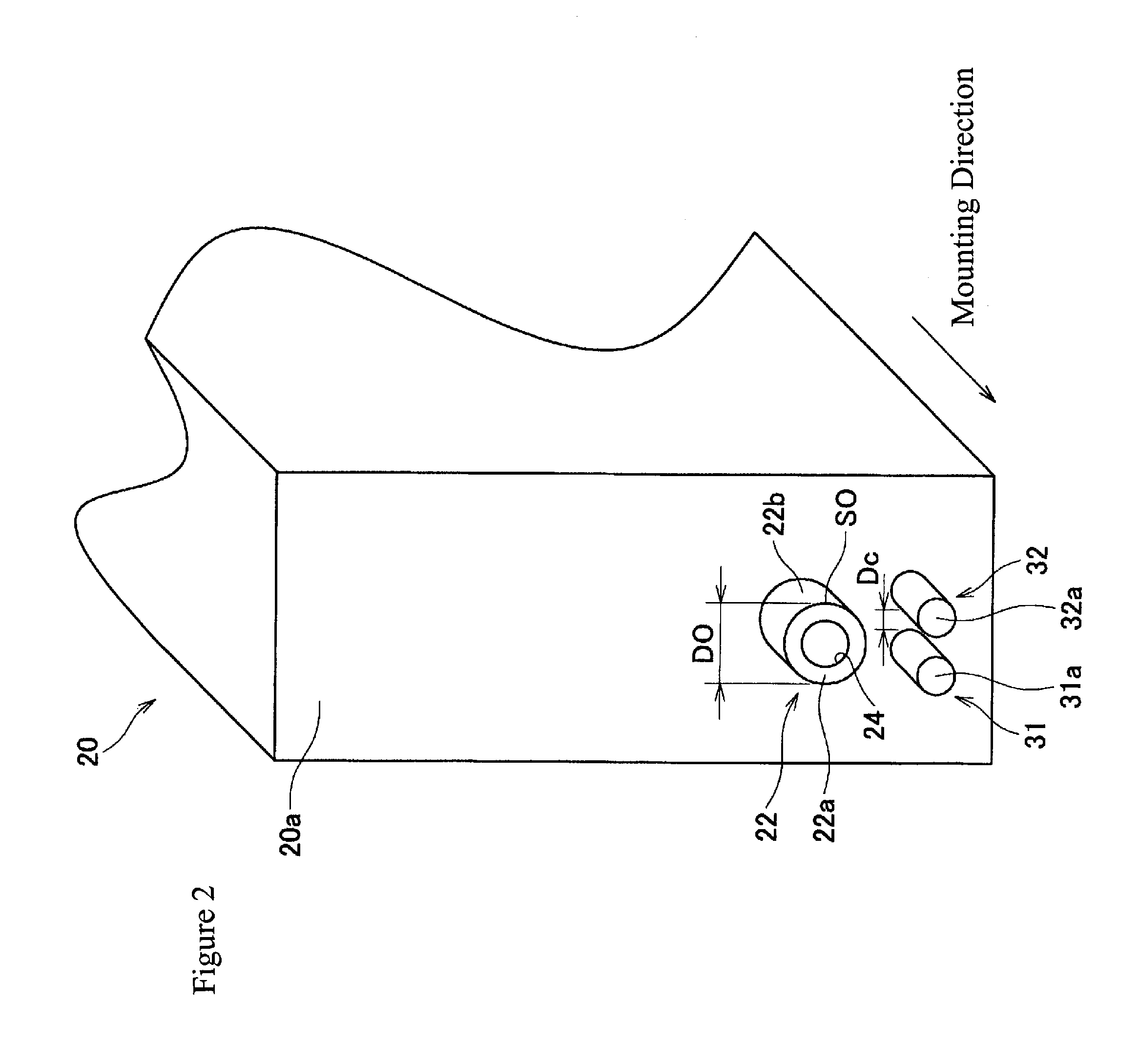
[0030]Embodiments of the present invention, and their features and advantages, are understood by referring to FIGS. 1-12, like numerals being used for like corresponding parts in the various drawings.

[0031]Referring to FIG. 1, an inkjet printer 1 may comprise an inkjet head 2, a mounting portion 16, a flexible tube 15, a carriage 5, a feeding mechanism 6, and a purge device 7. Inkjet head 2 also may comprise a plurality of nozzles 2a configured to eject ink toward a recording paper P, and mounting portion 16 may be configured to mount an ink cartridge 20. Inkjet head 2 and ink cartridge 20 may be in fluid communication with each other through tube 15 when ink cartridge 20 is mounted to mounting portion 16. Carriage 5 may be configured to reciprocate with inkjet head 2, feeding mechanism 6 may be configured to feed recording paper P, and purge device 7 may be configured to draw out air or thickened ink from the inside of inkjet head 2.

[0032]During a printing operation, inkjet head 2 ...


PUM


Abstract

An ink cartridge includes a wall, and an ink supply portion positioned at the wall. The ink supply portion has an ink supply opening formed therein. The ink cartridge also includes a plurality of protrusions which includes a first protrusion and a second protrusion, and each of the first protrusion and the second protrusion extend from the wall. In an embodiment, a distance between the first protrusion and the second protrusion is greater than 0 mm and less than a diameter of the ink supply opening. In another embodiment, the distance between the first protrusion and the second protrusion is greater than 0 mm and less than a diameter of the ink supply opening.

Description

[0001]The present application claims priority from Japanese Patent Application No. JP-2006-095468, which was filed on Mar. 30, 2006, and Japanese Patent Application No. JP-2006-347861, which was filed on Dec. 25, 2006, the disclosures of which are incorporated herein by reference in their entirety.BACKGROUND OF THE INVENTION[0002]1. Field of the Invention[0003]The present invention relates generally to ink cartridges and inkjet printers which use such ink cartridges.[0004]2. Description of Related Art[0005]A known inkjet recording system includes an inkjet recording apparatus and a plurality of ink cartridges which are mounted side by side to a mounting portion of the inkjet recording apparatus. An ink supply opening is formed at one surface of the ink cartridge, and an ink supply needle is provided in the inkjet recording apparatus and is inserted through the ink supply opening when the ink cartridge is mounted to the inkjet recording apparatus, which causes ink within the ink cart...

Claims


Application Information

Patent Timeline
IPC IPC(8): B41J2/175
CPCB41J2/17553
Inventor SUGAHARA, HIROTOHATTORI, SHINGO
Owner BROTHER KOGYO KK
Why Eureka
Try Eureka