

Application device, application method, and computer storage medium
The technology of a processing device and a processing method, which is applied to the device for applying liquid to the surface, the pretreatment surface, the coating layer, etc., can solve the problems such as the inability to obtain a thin film, and achieve the effect of suppressing dripping
- Summary
- Abstract
- Description
- Claims
- Application Information
AI Technical Summary
Problems solved by technology
Method used
Image

Examples
no. 1 Embodiment approach
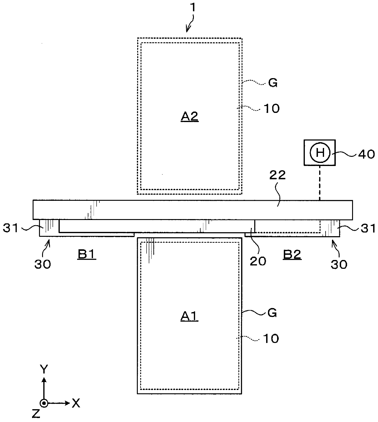
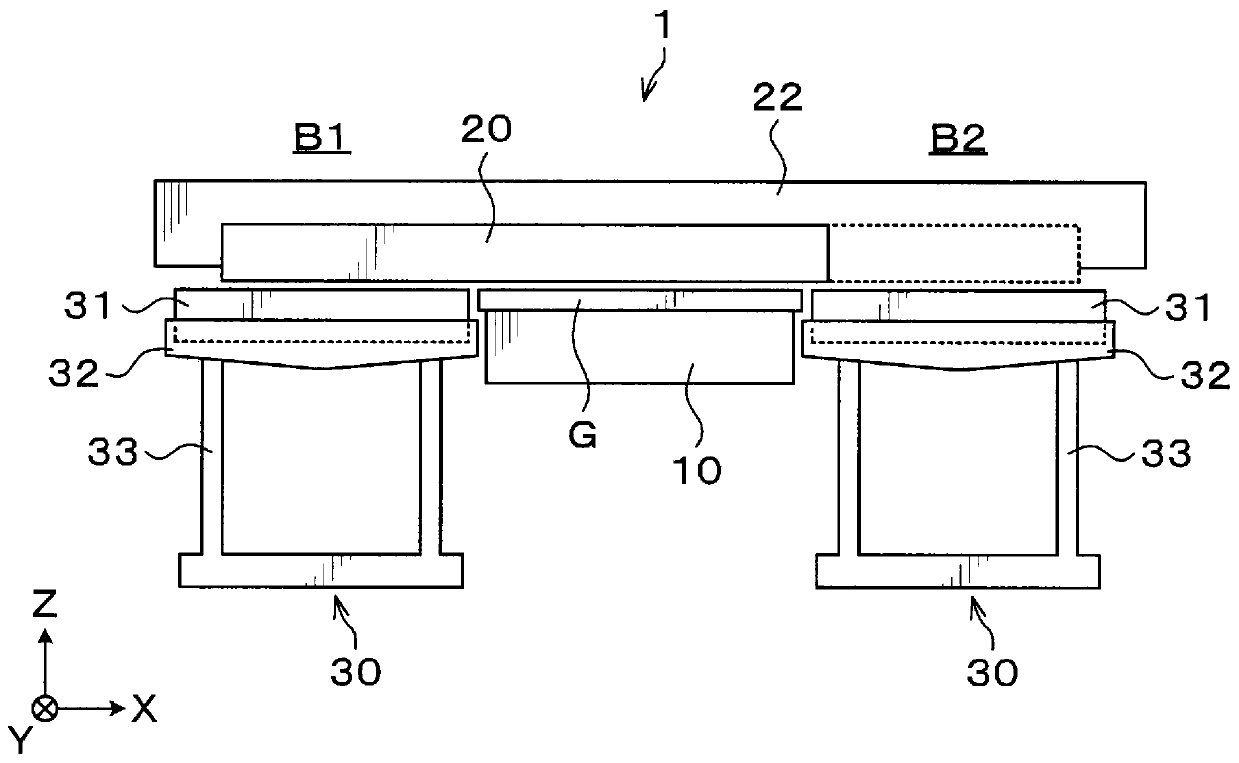
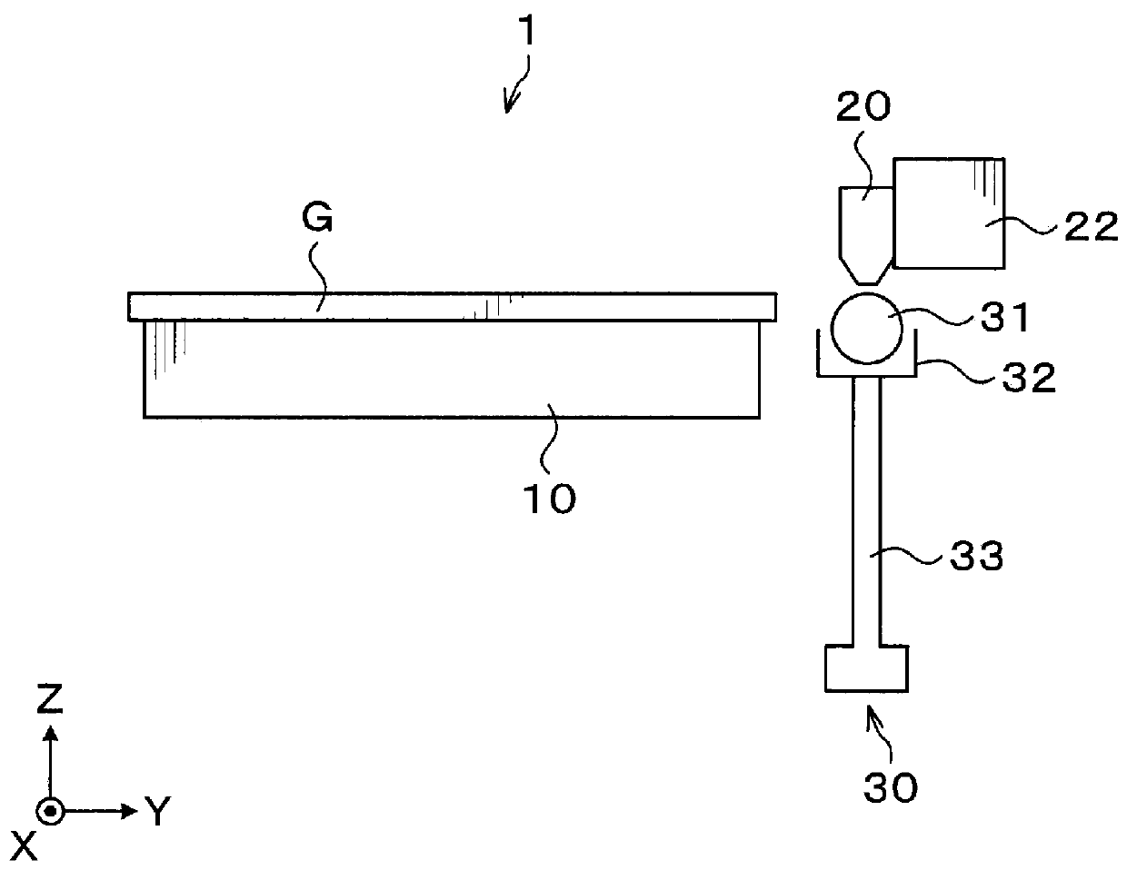
[0052] Next, a coating treatment device according to a first embodiment of the present invention will be described. figure 1 It is a plan view showing the schematic structure of the coating processing apparatus 1 of 1st Embodiment. figure 2 and image 3 It is a side view showing the schematic structure of the coating processing apparatus 1 of 1st Embodiment. In addition, in the drawings shown below, in order to clarify the positional relationship, the X-axis direction, the Y-axis direction, and the Z-axis direction orthogonal to each other are defined, and the positive direction of the Z-axis is vertically upward.
[0053] The coating processing apparatus 1 has: a mounting table 10 as a holding portion for holding the glass substrate G; a coating nozzle 20 for discharging the coating liquid to the glass substrate G; and receiving the coating liquid discharged from the end of the coating nozzle 20 The liquid receiving part 30.
[0054] The mounting table 10 adsorbs and hold...
no. 2 Embodiment approach
[0082] Next, a coating treatment device according to a second embodiment of the present invention will be described. Figure 9 and Figure 10 It is a side view showing the schematic structure of the coating processing apparatus 1 of 2nd Embodiment.
[0083] The second embodiment differs from the first embodiment in the structure of the liquid receiving unit of the coating treatment device 1 . That is, in the coating processing apparatus 1 of the second embodiment, the liquid receiving unit 100 is provided instead of the liquid receiving unit 30 of the first embodiment.
[0084] The liquid receiving unit 100 is provided on both sides of the glass substrate G held by the stage 10 on the outside in the X-axis direction. Each liquid receiving unit 100 has: a cap 101 that is a closure that closes the discharge port at the end of the coating nozzle 20 ; and a support frame 102 that is a support structure that supports the cap 101 from below.
[0085] The cover 101 is extended in ...
no. 3 Embodiment approach
[0089] Next, a coating treatment device according to a third embodiment of the present invention will be described. Figure 12 It is an explanatory diagram showing how the application liquid P is received by the liquid receiving part 110 in the third embodiment.
[0090] The third embodiment differs from the first embodiment in the configuration of the liquid receiving unit in the coating treatment device 1 . That is, in the coating processing apparatus 1 of the third embodiment, the liquid receiving unit 110 is provided instead of the liquid receiving unit 30 of the first embodiment.
[0091] The liquid receiving parts 110 are provided on both sides of the glass substrate G held by the stage 10 outside in the X-axis direction. Each liquid receiving unit 110 includes a recovery pan 111 that is a recovery container that recovers coating liquid P discharged from the end of the coating nozzle 20 , and a support frame (not shown) that is a support structure that supports the reco...
PUM
 Abstract
Description
Claims
Application Information