
Large-sized hydraulic speed change floating box flap valve
一种液压变速、浮箱的技术,应用在功能阀类型、应用、升阀等方向,能够解决封水橡皮更换频繁、影响泵站工作环境、装配过程麻烦等问题,达到装配过程简单方便快捷、保证正常工作环境、安装和维修方便的效果
- Summary
- Abstract
- Description
- Claims
- Application Information
AI Technical Summary
Problems solved by technology
Method used
Image

Examples
Embodiment Construction
[0036] The present invention will be described in further detail below in conjunction with the accompanying drawings and specific embodiments.
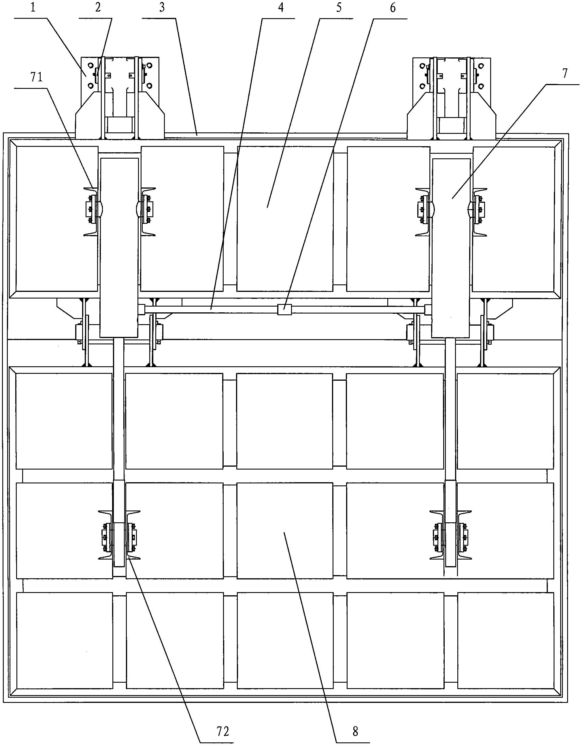
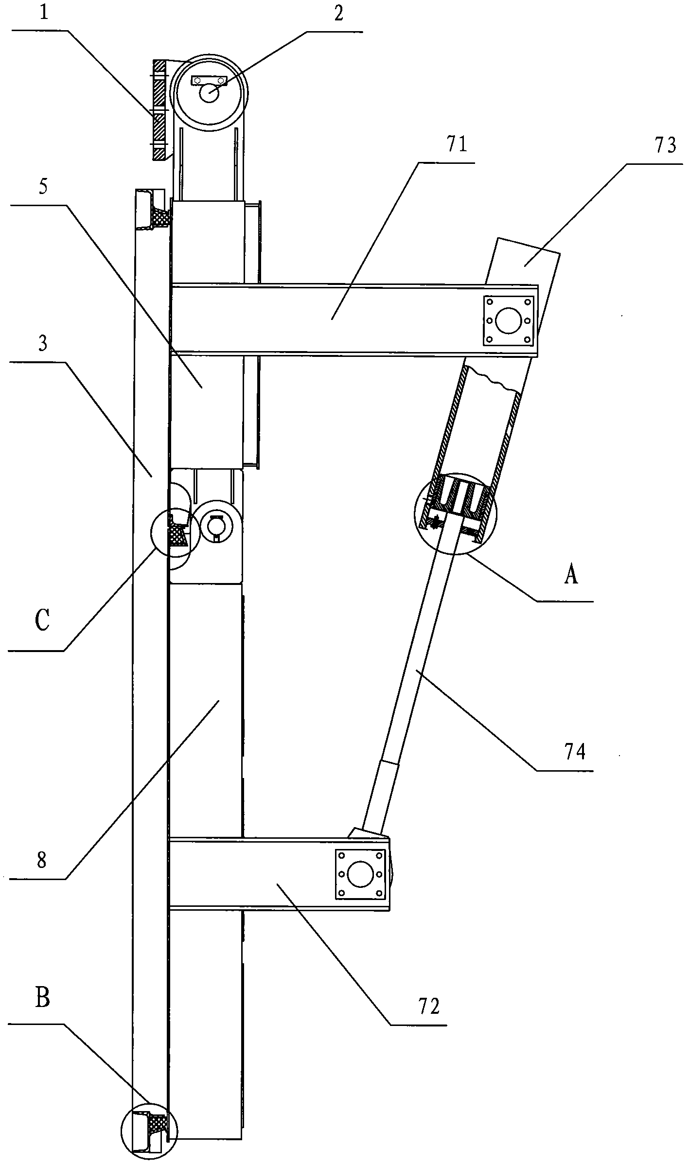
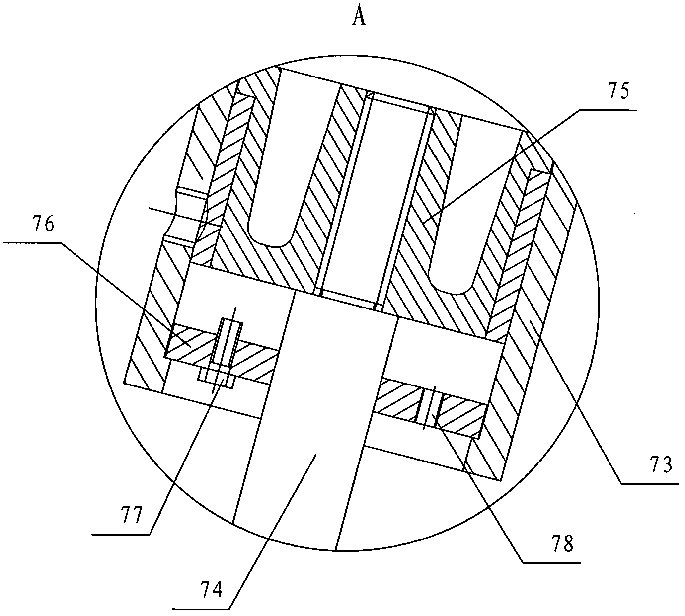
[0037] Depend on figure 1 , figure 2 and image 3 As can be seen from the structural schematic diagram of the large-scale hydraulic variable speed buoyant flap door of the present invention shown, it includes hinge seat 1, door seat 3, upper door leaf 5 and lower door leaf 8, and described door seat 3 and hinge seat 1 are all fixed on the pump On the base of the station, the upper door leaf 5 is hinged with the hinge seat 1 through the pin shaft 2, the lower door leaf 8 is hinged with the upper door leaf 5, and the upper door leaf 5 and the lower door leaf 8 are connected to the door through a sealing structure. Seat 3 can be sealed contact fit. The upper door leaf 5 is connected to the lower door leaf 8 through at least one hydraulic mechanism 7 , one end of the hydraulic mechanism 7 is hinged to the upper door leaf 5 , and the o...
PUM
 Abstract
Description
Claims
Application Information