Distance measuring apparatus and method
a technology of distance measurement and measuring apparatus, which is applied in the direction of distance measurement, instruments, television systems, etc., can solve the problems of affecting the reliability of the af mechanism, the accuracy of the measurement, and the deviation of the actual distance obtained by the sensor from the actual distance to the subject, so as to improve the reliability of the distance measurement result and improve the performance of the imaging apparatus.
- Summary
- Abstract
- Description
- Claims
- Application Information
AI Technical Summary
Benefits of technology
Problems solved by technology
Method used
Image
Examples
first embodiment
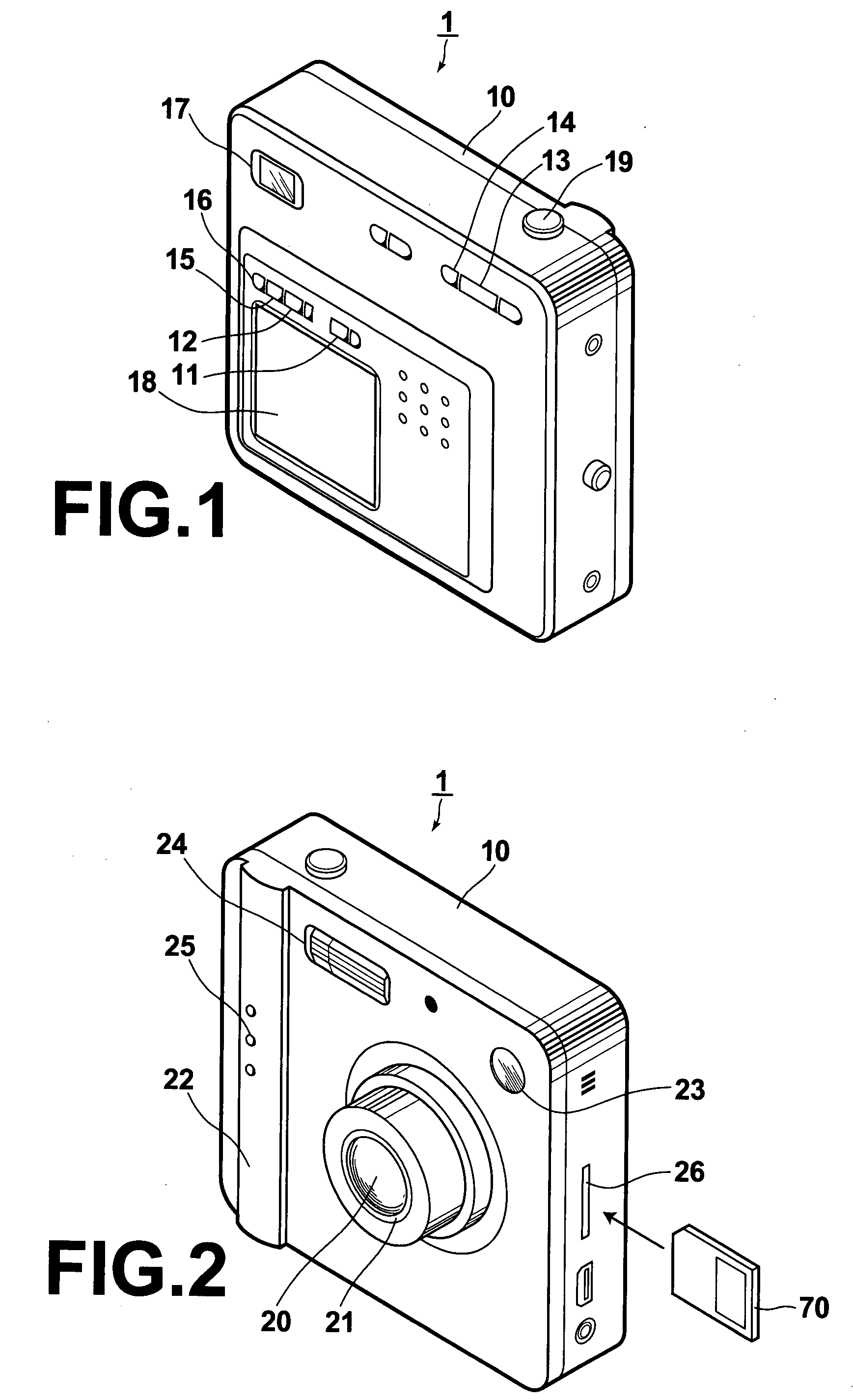
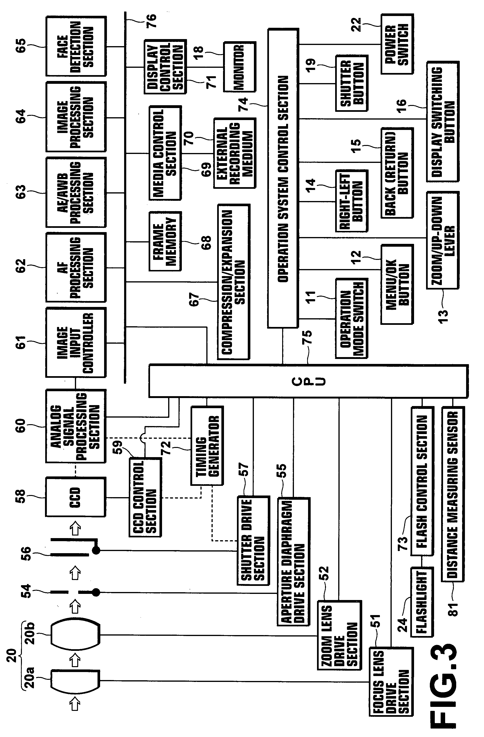
[0054]FIGS. 1 and 2 illustrate an example digital camera. FIG. 1 is an external view thereof viewed from the rear side, and FIG. 2 is an external view thereof viewed from the front side. An operation mode switch 11; a menu / OK button 12; a zoom / up-down lever 13; a right-left button 14; a back (return) button 15; display switching button 16; a finder 17 for imaging; and a monitor 18 for imaging and playback are provided on the rear side of the main body 10 of the digital camera 1 as the operation interface for the user as shown in FIG. 1. In addition, a shutter button 19 is provided on the upper side of the main body 10.
[0055]The operation mode switch 11 is a slide switch for selecting still image recording mode, moving picture imaging mode, or playback mode. The menu / OK button 12 is a button for selecting imaging mode, flash emission mode, or displaying various menus on the monitor 18 for setting the number of recording pixels, sensitivity and the like, which are sequentially selecte...
second embodiment
[0088]In the first embodiment, a method, in which the way of obtaining the subject distance is changed according to the size of a face, is described. In the second embodiment, a method in which peak values are detected from focus evaluation values, and either the subject distance “A” calculated from the size of a face or subject distance “B” measured by the distance measuring sensor 81 is adopted will be described. The external view, functional block, major process sequence, and focusing process of the digital camera 1 in the second embodiment are identical to those in the first embodiment explained using FIGS. 1 to 5. Therefore, they will not be elaborated upon further here, and only a subject distance detection means will be described.
[0089]FIG. 7 is a flowchart illustrating the flow of a subject distance detection process according to the second embodiment. First, the CPU 75 performs various control operations for performing rough searching process over the entire range from the ...
third embodiment
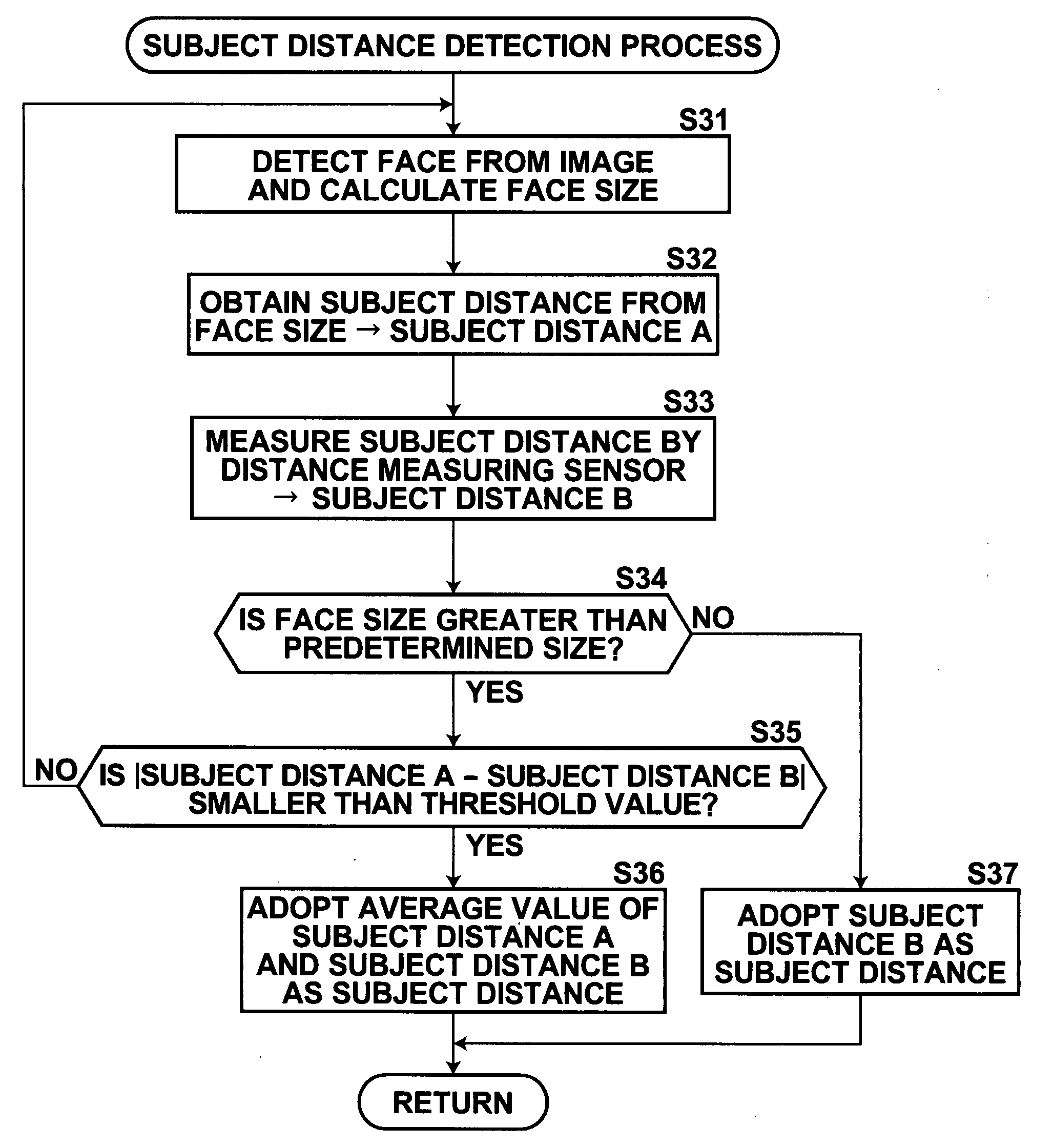
[0098]In the third embodiment, a method in which the subject distance is determined by varying a threshold value, for determining whether the difference between the subject distance “A” calculated from the size of a face and subject distance “B” measured by the distance measuring sensor 81 is within an allowable range, according to the size of a face will be described. The external view, functional block, major process sequence, and focusing process of the digital camera 1 in the third embodiment are identical to those in the first embodiment explained using FIGS. 1 to 5. Therefore, they will not be elaborated upon further here, and only a subject distance detection means will be described.
[0099]FIG. 10 is a flowchart illustrating the flow of a subject distance detection process according to the third embodiment. First, the CPU 75 moves the focus lens 20a to a predetermined position through the focus lens drive section 51, and causes the face detection section 65 to detect a face of...
PUM
 Abstract
Description
Claims
Application Information
 - R&D
- Intellectual Property
- Life Sciences
- Materials
- Tech Scout
- Unparalleled Data Quality
- Higher Quality Content
- 60% Fewer Hallucinations
Browse by: Latest US Patents, China's latest patents, Technical Efficacy Thesaurus, Application Domain, Technology Topic, Popular Technical Reports.
© 2025 PatSnap. All rights reserved.Legal|Privacy policy|Modern Slavery Act Transparency Statement|Sitemap|About US| Contact US: help@patsnap.com


