Method for dynamically adjusting the operating parameters of a tof camera according to vehicle speed

a tof camera and operating parameter technology, applied in the field of time of flight sensor system, can solve the problems of almost impossible to assign individually separate tof modulation frequencies for each sensor product, and the cross-interference of modulated illumination between multiple tof sensors has not been considered, so as to achieve the effect of extending the camera range, avoiding cross-interference of modulated illumination among multiple tof sensors, and allowing more time for speed adjustmen

Active Publication Date: 2014-06-05
TEXAS INSTR INC
View PDF2 Cites 126 Cited by
  • Summary
  • Abstract
  • Description
  • Claims
  • Application Information

AI Technical Summary

Benefits of technology

[0015]Depth sensor technology is a cutting edge new technology. The TOF sensor's cross-interference from modulated illumination has not been considered mainly because multiple TOF cameras have not been adopted to any great degree. As a result, TOF modulation frequencies have been manually reconfigured. However, for example, if TOF technology is widely applied to automobile applications e.g. for front and rear scene analysis, it is almost impossible to assign individually separate TOF modulation frequencies for each sensor product. The given technique allows a dynamic change of TOF modulation frequency by detecting other TOF sensors' modulation frequencies. Thus, the cross-interference of modulated illumination among multiple TOF sensors can be avoided.
[0016]Additional functions are enabled by the capability of dynamically changing the IR modulating frequency. By adjusting the modulation frequency in relation to the vehicle's speed, the range of the TOF camera can be optimized for collision avoidance or speed control application. At higher speeds the camera's range is extended to allow more time for speed adjustment, and at slower speeds the range is reduced with a corresponding increase of the distance measurement's accuracy.
[0017]IR illumination power may also be dynamically adjusted according to speed and ambient light in order to minimize the noise level seen by the TOF.

Problems solved by technology

The TOF sensor's cross-interference from modulated illumination has not been considered mainly because multiple TOF cameras have not been adopted to any great degree.
However, for example, if TOF technology is widely applied to automobile applications e.g. for front and rear scene analysis, it is almost impossible to assign individually separate TOF modulation frequencies for each sensor product.

Method used


Image

  • Method for dynamically adjusting the operating parameters of a tof camera according to vehicle speed
  • Method for dynamically adjusting the operating parameters of a tof camera according to vehicle speed

Examples


Embodiment Construction

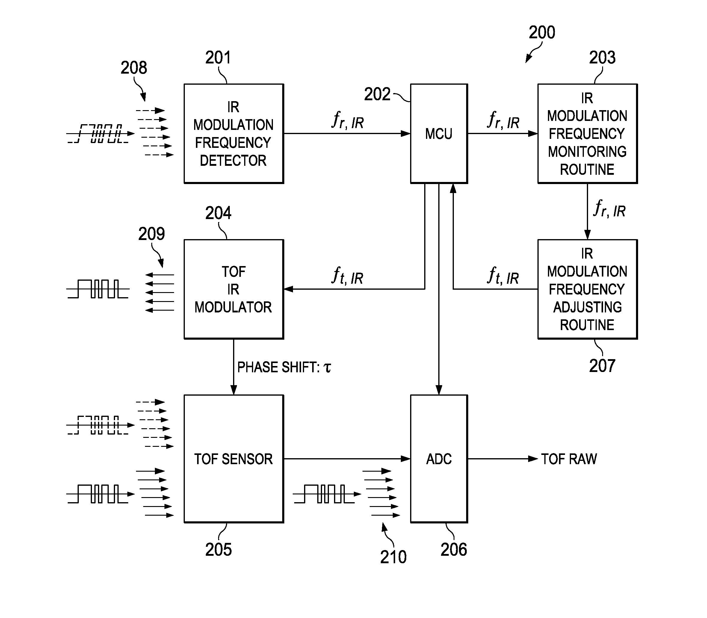
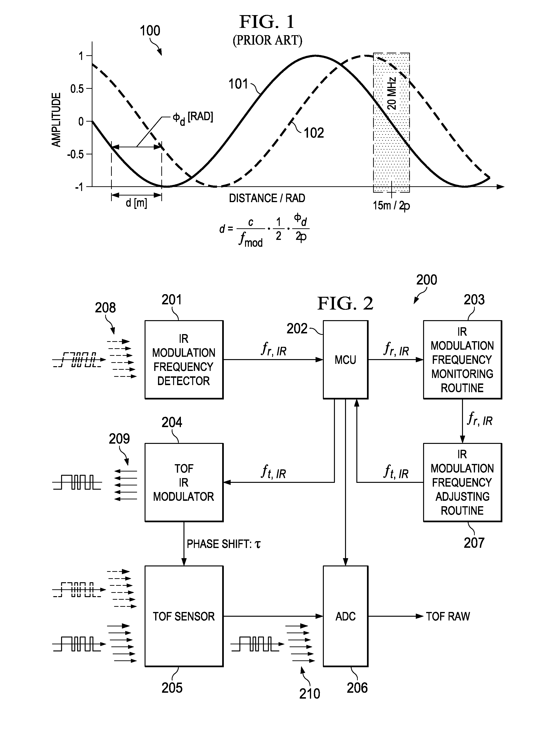
[0021]A TOF (Time Of Flight) sensor delivers a very accurate depth measurement and can be widely applied to applications within various environments. However, TOF sensor technology intrinsically has a cross interference problem among TOF sensors due to IR illuminations from multiple TOF sensors employing the same modulation frequency. Since IR modulation frequency is directly related to a covered depth range of TOF, there is the likelihood that the same modulation frequency of TOF IR illumination will be selected among TOF sensors in place.

[0022]For example, for applications targeting a mid range depth map, in many cases a 20 MHz IR modulation frequency is chosen. Interference from TOF sensors with the same IR modulation frequency (20 MHz) can significantly impact on depth accuracy of each sensor.

[0023]The described invention provides a method to avoid IR interference among TOF sensors by combining the IR modulation frequency detector with logic for dynamic adjustment of the IR tran...


PUM


Abstract

A method for adjusting the modulating frequency and the intensity of the IR illumination of a Time of Flight measurement system proportionally to the speed of movement and the ambient light level of the TOF system, thus adjusting the range of vision of the system dependent on speed. In an alternate embodiment the modulating frequency of a TOF measurement system is periodically adjusted to cover a larger range of vision of the TOF.

Description

TECHNICAL FIELD OF THE INVENTION[0001]The technical field of this invention is a Time of Flight sensor system.BACKGROUND OF THE INVENTION[0002]Acquiring 3D geometric information from real environments is an essential task for many applications in computer graphics. Prominent examples such as virtual and augmented environments and human machine interaction, e.g. for gaming, clearly benefit from simple and accurate devices for real-time range image acquisition. However, even for static scenes there is no low-price off-the-shelf system that provides full-range, high resolution distance information in real time. Laser triangulation techniques, which merely sample a scene row by row with a single laser device, are rather time-consuming and therefore impracticable for dynamic scenes. Stereo vision camera systems suffer from the inability to match correspondences in homogeneous object regions.[0003]Time-of-Flight (ToF) technology, based on measuring the time that light emitted by an illumi...

Claims


Application Information

Patent Timeline
Patent Type & Authority Applications(United States)
IPC IPC(8): G01S17/89G01S17/894
CPCG01S17/89G01C11/00G01S7/4865G01S17/93G01C15/002G01S17/894
Inventor KO, DONG-IK
Owner TEXAS INSTR INC
Why Eureka
Try Eureka