Apparatus and method for measuring three-dimensional shape of wood block

a three-dimensional shape and wood block technology, applied in the field of apparatus and a method for measuring three-dimensional shape of generally cylindrical wood blocks, can solve the problems of not having a true cylindrical surface, affecting the productivity of the veneer lathe, and the resolution of the three-dimensional shape of the wood block, so as to improve the accuracy of measuring, improve the resolution of measuring distances, and improve the accuracy

Active Publication Date: 2010-05-06
MEINAN MASCH WORKS INC
View PDF7 Cites 21 Cited by
  • Summary
  • Abstract
  • Description
  • Claims
  • Application Information

AI Technical Summary

Benefits of technology

[0013]According to the present invention, distances from the tentative spin axis of the block to the outer peripheral surface of the block, which define profile of the block, are measured by making use of the lines illuminated on the outer peripheral surface of the block. Since the illuminated lines formed by the light beams from the light emitting device lie on the outer peripheral surface of the block, the measurements of the distances from the tentative spin axis to the illuminated lines at a plurality of spaced points that correspond to the aforementioned plurality of cross-sections of the block represent accurate block profiles including the shapes of various defects or irregularities present on the outer peripheral surface of the block. Thus, the distances between the tentative spin axis of the block and the outer peripheral surface of the block can be measured with high accuracy. Decreasing the interval of the spaced points along the length of the block, the resolution in measuring the distances can be increased.
[0014]The present invention improves the accuracy in measuring the distances from the tentative spin axis to the outer peripheral surface of the block. Additionally, the resolution in measurement of the distance is improved. Therefore, three-dimensional shape of the block that is comprised of a large number of profiles in section of the block across its tentative spin axis can be measured with high accuracy throughout its length, with the result that optimum spin axis and the maximum radius point of the block can be located precisely, which makes possible improving the yield in veneer peeling and operating efficiency of the veneer lathe.

Problems solved by technology

As is well known to those skilled in the art, a block that is made by cross-cutting a natural log to any desired length does not have a true cylindrical surface.
The time spent before actual peeling begins is a downtime affecting the productivity of the veneer lathe.
According to the apparatuses of the above Publications, however, the resolution in measurement of three-dimensional shape of a wood block (or profiles of the block in a plurality of sections across the tentative spin axis of the block) is poor in that the resolution is limited by the number of sensors or detector arranged along the block length.
Specifically, any defective part or irregularities of a wood block such as knot, burl, hole, recess, etc. present between any two adjacent sensors or detectors cannot not be recognized.
When contact type sensors are used in measuring three-dimensional shape of a wood block having various irregularities such as projection on the peripheral surface thereof, each sensor can only detect the highest point of a projection in its detecting region without determining accurately the profile of the other parts than the highest point.
Incapability of accurately measurement of three-dimensional profile of a wood block throughout its length makes it difficult to find an accurate position of the optimum spin axis of the block and a point on outer peripheral surface of the block having the largest distance from the spin axis that are necessary for improvement of yield and working efficiency in veneer peeling.

Method used


Image

  • Apparatus and method for measuring three-dimensional shape of wood block
  • Apparatus and method for measuring three-dimensional shape of wood block
  • Apparatus and method for measuring three-dimensional shape of wood block

Examples


Embodiment Construction

[0032]The following will describe the preferred embodiment of apparatus for measuring three-dimensional shape of a wood block according to the present invention while having reference to the accompanying drawings.

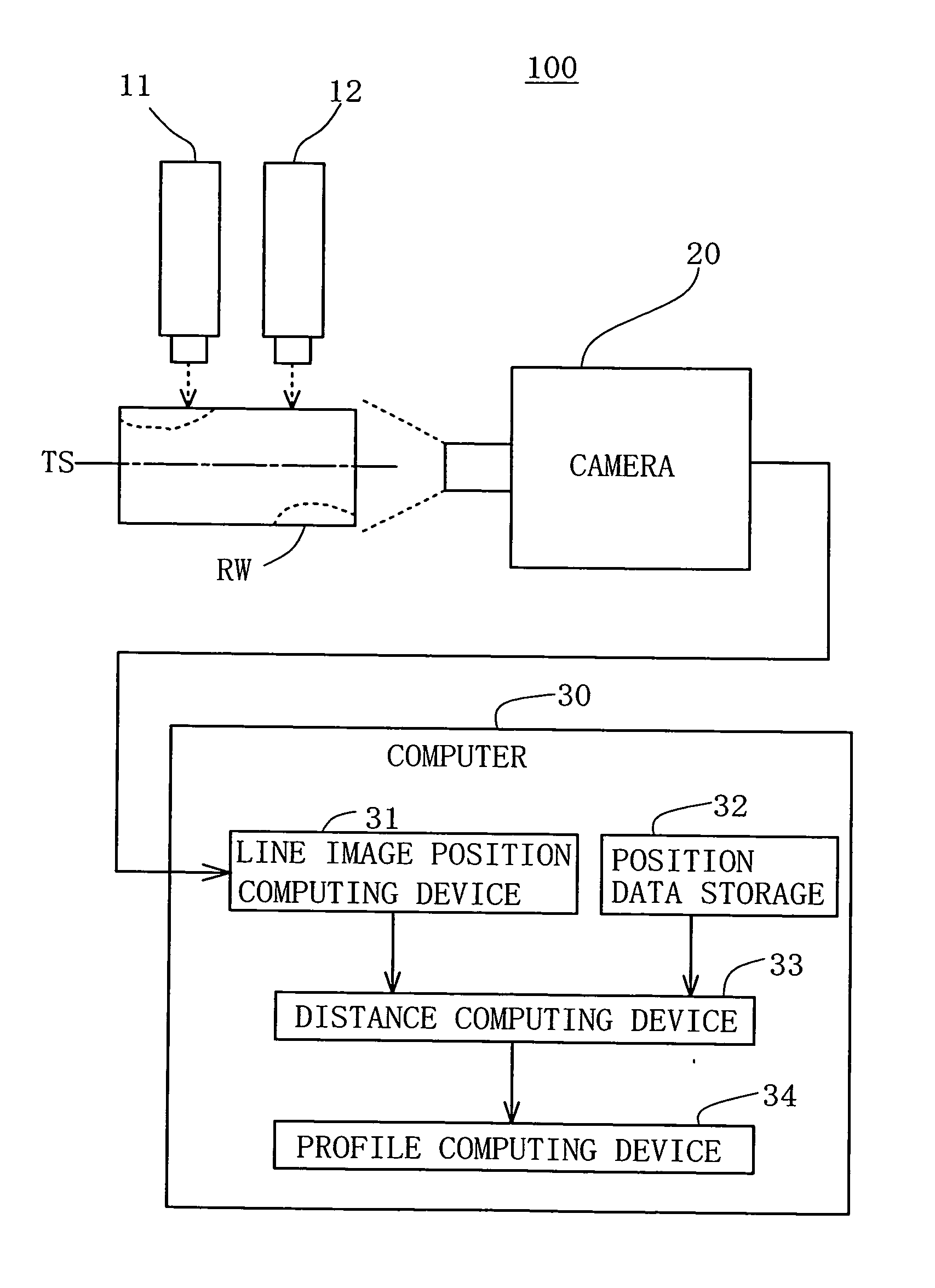
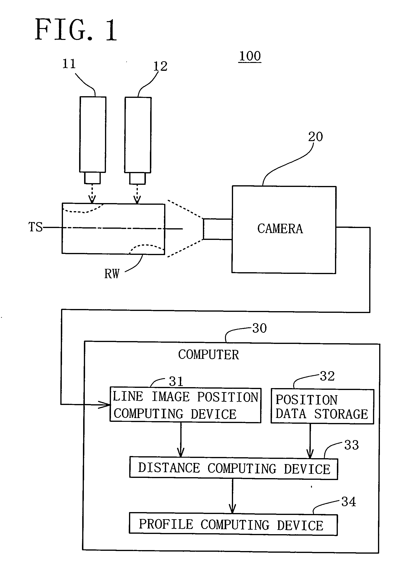
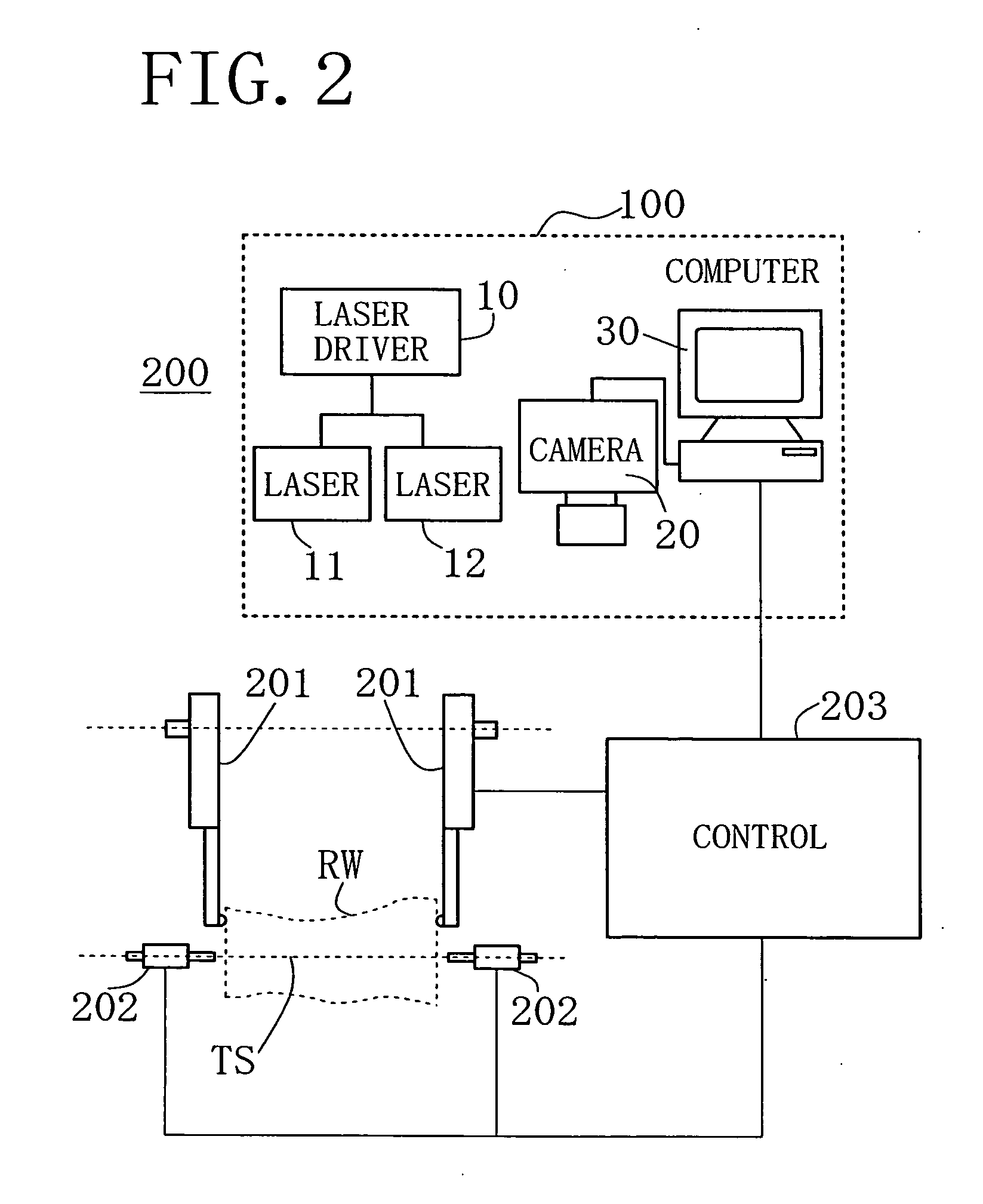
[0033]Referring firstly to FIGS. 1 and 2, the three-dimensional shape measuring apparatus, which is designated generally by numeral 100, includes a pair of lasers 11, 12 (or light emitting devices) driven by a laser driver 10, a camera 20 (or an imaging device) and a computer 30. As shown in FIGS. 4A and 4B, the camera has a lens 21 and an area sensor 22.

[0034]Referring to FIG. 2, the lathe charger, which is generally designated by numeral 200, includes a pair of swing arms 201, a pair of spindles 202 and a control 203 for controlling the operation of the swing arms 201 and the spindles 202, as well as the above three-dimensional shape measuring apparatus 100. Reference symbol RW designates a wood block that is cut from a natural log to a predetermined length. The swing arm...


PUM


Abstract

An apparatus and a method for measuring three-dimensional shape of a wood block are disclosed. A planar light beam is projected by a light emitting device against a wood block rotatably supported on its tentative spin axis in such a way that two continuous lines extending parallel to the tentative spin axis for the entire block length are illuminated on the outer peripheral surface of the block. The block with the illuminated lines is photographed at a plurality of its angular positions by a imaging device. Based on data of the photographed line images, distances between the tentative spin axis and each of the illuminated lines on the outer peripheral surface of the block are computed at a plurality of cross-sections of the block along the tentative spin axis. Distances from the tentative spin axis to the outer peripheral surface of the block, including shapes of various irregularities on the surface of the block, are measured.

Description

BACKGROUND OF THE INVENTION[0001]The present invention relates generally to an apparatus and a method for measuring three-dimensional shape of a generally cylindrical wood block. More specifically, the invention relates to an apparatus and a method for measuring the distances of the wood block from a tentative spin axis on which the block is rotatably supported to the outer peripheral surface of the block at a plurality of angular positions thereof thereby to determine profiles of the block in a plurality of cross-sections thereof perpendicular to and spaced along the tentative spin axis of the block.[0002]Wood veneer which is used for manufacturing various kinds of wood products such as plywood is cut or peeled from a generally cylindrical wood block by a veneer knife which is fed into the block from its peripheral surface toward the spin axis of the block. Such cutting or peeling is done by a machine called veneer lathe. In a veneer lathe, a wood block is rotatably supported by sp...

Claims


Application Information

Patent Timeline
Patent Type & Authority Applications(United States)
IPC IPC(8): G06K9/00
CPCG01B11/2522
Inventor HIRAOKA, NORIYUKI
Owner MEINAN MASCH WORKS INC
Why Eureka
Try Eureka