Ribbon Feeder and Printer

a printer and ribbon retainer technology, applied in printing, inking apparatus, printing mechanisms, etc., can solve the problems of destroying print quality in some cases, and the ribbon retainer portion that is mounted on the distal end of the tension arm does not have the function of removing wrinkles, etc., to achieve high print quality, easy generation, and high accuracy

Active Publication Date: 2007-10-04
CITIZEN WATCH CO LTD
View PDF8 Cites 82 Cited by
  • Summary
  • Abstract
  • Description
  • Claims
  • Application Information

AI Technical Summary

Benefits of technology

[0011] According to the present invention, as described above, the smoothing function is added to the ribbon feeder, so that wrinkles in a film that are easily generated in a printer that uses a wide transfer film ribbon, in particular, can be eliminated, and high print quality can be maintained. Since the smoothing function is incorporated in the ribbon tension detecting means, the ribbon feeder can be formed compactly. Since the smoothing member is provided in the ribbon tension detecting means, moreover, the tension of the transfer film ribbon that acts on the ribbon tension detecting means can be utilized without unevenness or attenuation. Thus, the ribbon tension can be detected with high accuracy.
[0012] In the ribbon feeder according to the present invention, the torque dampers in the form of coil springs are used in place of a conventional tension arm to absorb the looseness of the ribbon. Therefore, the ribbon feeder can be compactified without using a lon...

Problems solved by technology

Therefore, the ribbon may wrinkle or rub against the paper sheet, so that the print quality may be ruined in some cases.
Further, the ribbon retai...

Method used


Image

  • Ribbon Feeder and Printer
  • Ribbon Feeder and Printer
  • Ribbon Feeder and Printer

Examples


first embodiment

[0026] a ribbon feeder according to the present invention will now be described with reference to FIGS. 1 to 9.

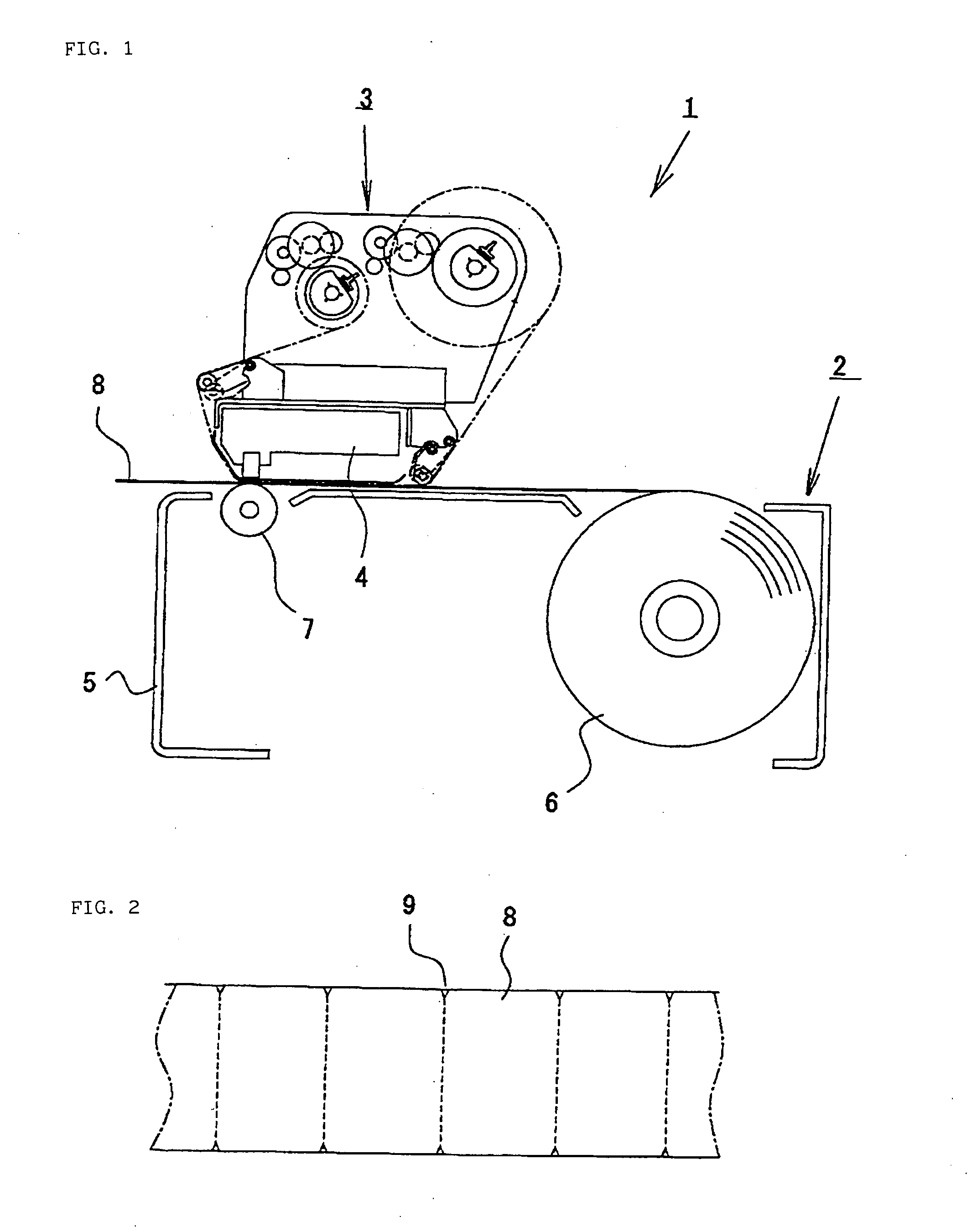
[0027] An outline of a printer that uses a thermal transfer film ribbon will be described with reference to FIG. 1.

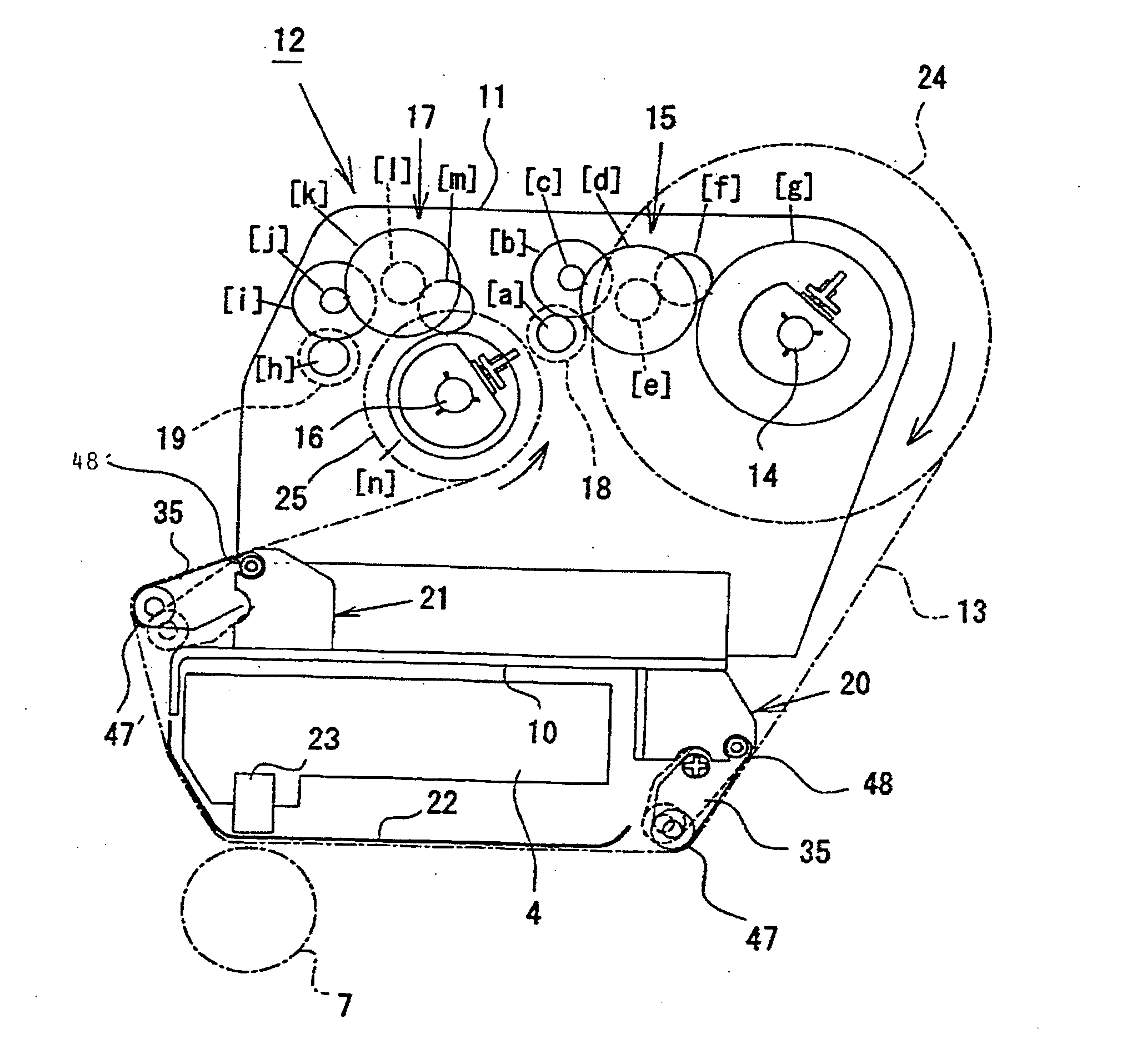
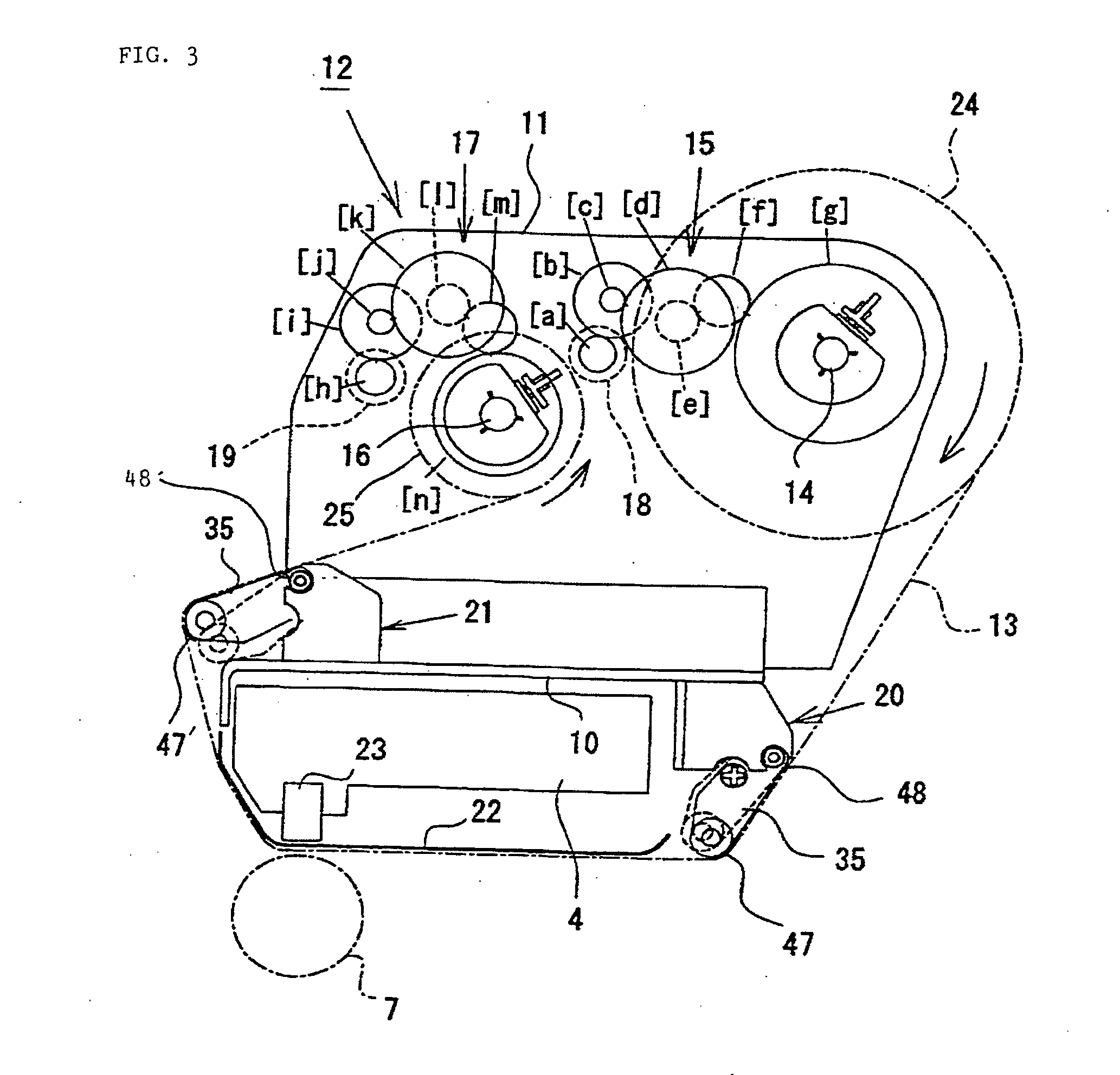
[0028] A printer 1 comprises a body unit 2, a ribbon feeder 3, and a head unit 4. The ribbon feeder 3 is placed on the body unit 2. The ribbon feeder 3 is configured so that it can be lifted off the body unit 2 at the time of replacement or inspection. A paper roll 6 and a platen 7 are attached to a frame 5 of the body unit 2. The platen 7 is rotated by a motor (not shown) for rotation. The top face of the frame 5 constitutes a paper transport path. A paper sheet 8 drawn out from the paper roller 6 is delivered in the leftward direction of FIG. 1 on the paper transport path as the platen 7 rotates. In this embodiment, the paper sheet 8 is a label sheet with a width of about 120 mm, which has notches 9 formed on its opposite lateral sides and arranged at given ...

third embodiment

[0075] the ribbon feeder according to the present invention will now be described with reference to FIG. 11.

[0076]FIG. 11 shows a plate-like lever body 35 that is taken out from the ribbon feeder according to the third embodiment. In this drawing, an operating shaft 55 penetrates a first roller 47 that constitutes the plate-like lever body 35. The left-hand end of the operating shaft 55 is supported by a left-hand shaft support member 46a for rotation around its axis. On the other hand, the right-hand end of the operating shaft 55 is eccentrically connected to a control knob 55 that penetrates a right-hand shaft support member 46b from outside to inside. Thus, an axis n of the operating shaft 55 of the first roller 47 is not in alignment with an axis m of a shaft of the control knob 55, as shown in FIG. 11.

[0077] If the control knob 55 is manually rotated, therefore, the operating shaft 55 rocks around a central axis between the left- and right-hand shaft support members 46a and 46...


PUM


Abstract

Ribbon tension detecting means (20, 21), which are formed of a plate-like lever body (35) each, are located individually on the upstream side and the downstream side of a platen (7) with respect to its travel. The plate-like lever body (35) has first and second rollers (47, 48) on the upstream and downstream sides with respect to travel of a ribbon, and swings around an axis of rotation of the second roller (48), depending on a tension of the ribbon traveling guided by the rollers (47, 48). If the amount of its swing is not less than or not more than a fixed value, a ribbon feed motor (18) or a ribbon take-up motor (19) is driven. Further, the ribbon tension detecting means (20, 21) are provided with a smoothing member which touches the ink ribbon (13) to remove wrinkles from the ink ribbon (13).

Description

TECHNICAL FIELD [0001] The present invention relates to a ribbon feeder of a printer that uses an ink ribbon, and more particularly, to a printer that uses a transfer film ribbon and a ribbon feeder provided with ribbon tension detecting means therefor and a smoothing member in the ribbon tension detecting means. BACKGROUND ART [0002] In a printer that uses a transfer film ribbon (hereinafter referred to as ribbon) such as a thermal transfer film, the ribbon and a paper sheet are delivered in pressure contact between a head and a platen. If the ribbon tension varies as this is done, the feed of the ribbon is not concurrent with the feed of the paper sheet. Therefore, the ribbon may wrinkle or rub against the paper sheet, so that the print quality may be ruined in some cases. [0003] In order to reduce the variation of the ribbon tension, in a conventional printer such as the one described in Japanese Paten Application Laid-Open No. 62-113581, a motor for a ribbon feed shaft is driven...

Claims


Application Information

Patent Timeline
IPC IPC(8): B41J33/00B41J17/08B41J17/10B41J17/30B41J33/52B41J35/04
CPCB41J17/30B41J17/08
Inventor UEDA, MASAHIKOMORITA, SEIJISAKURAI, HIROSHI
Owner CITIZEN WATCH CO LTD
Why Eureka
Try Eureka