

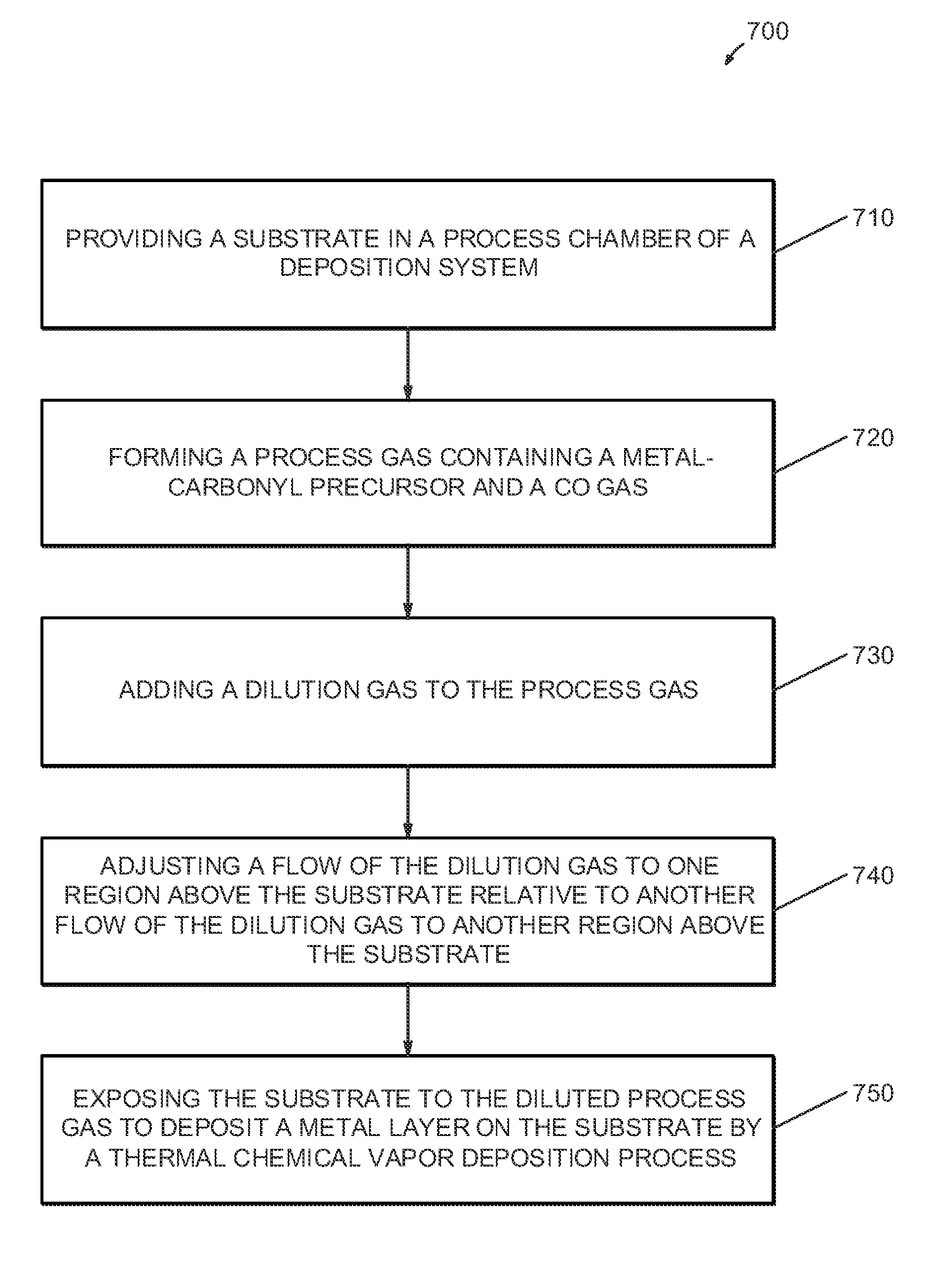
Method for reducing carbon monoxide poisoning in a thin film deposition system
a thin film and carbon monoxide technology, applied in chemical vapor deposition coatings, coatings, plasma techniques, etc., can solve the problems of poor deposition rate, inability to deposition metal films, low rate of current deposition systems, etc., and achieve the effect of improving the transport of precursor vapor
- Summary
- Abstract
- Description
- Claims
- Application Information
AI Technical Summary
Benefits of technology
Problems solved by technology
Method used
Image

Examples
Embodiment Construction
[0018] In the following description, in order to facilitate a thorough understanding of the invention and for purposes of explanation and not limitation, specific details are set forth, such as a particular geometry of the deposition system and descriptions of various components. However, it should be understood that the invention may be practiced in other embodiments that depart from these specific details.
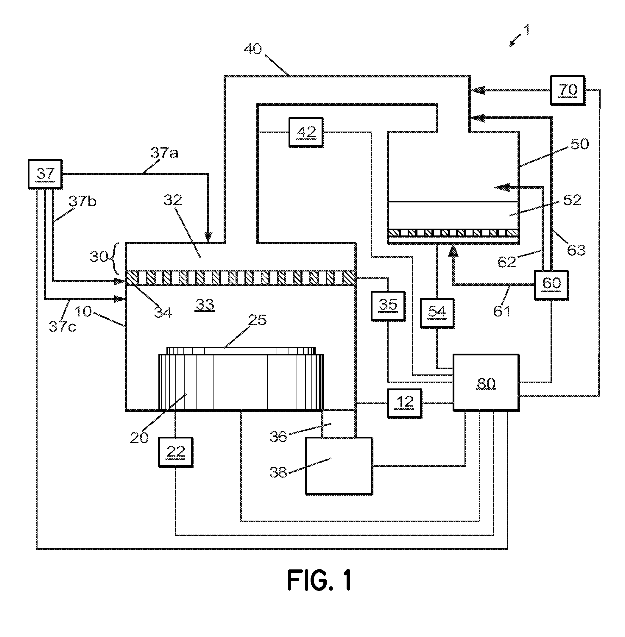
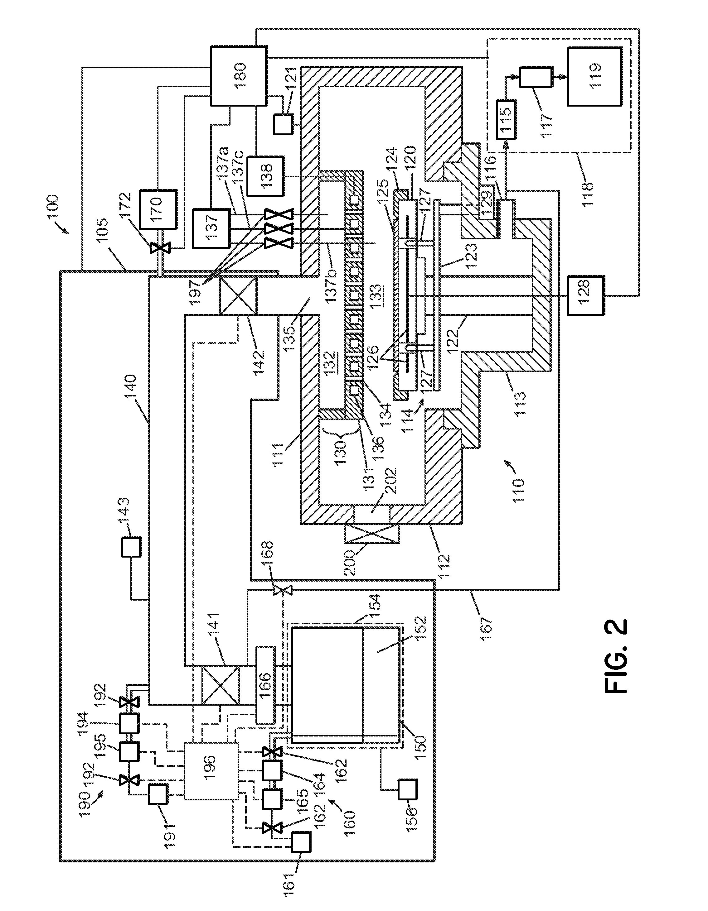
[0019] Referring now to the drawings, wherein like reference numerals designate identical or corresponding parts throughout the several views, FIG. 1 schematically illustrates a thermal chemical vapor deposition system 1 for depositing a metal layer on a substrate from a metal carbonyl precursor, according to one embodiment. While other metal carbonyl precursors may be used, embodiments of the invention may henceforth be described with particular reference to ruthenium carbonyl precursors, such as Ru3(CO)12, with the understanding that the invention is not so limited. The deposi...
PUM
| Property | Measurement | Unit |
|---|---|---|
| temperature | aaaaa | aaaaa |
| temperature | aaaaa | aaaaa |
| pressure | aaaaa | aaaaa |
Abstract
Description
Claims
Application Information