Double-sided connector capable of easily and accurately positioning a connection member
a technology of connecting member and double-sided connector, which is applied in the direction of coupling contact member, fixed connection, coupling device connection, etc., can solve the problems of reducing working efficiency, and achieve the effect of easy and simple positioning, easy and simple exchange of connection members, and easy and simple assembly and disassembly
- Summary
- Abstract
- Description
- Claims
- Application Information
AI Technical Summary
Benefits of technology
Problems solved by technology
Method used
Image
Examples
first embodiment
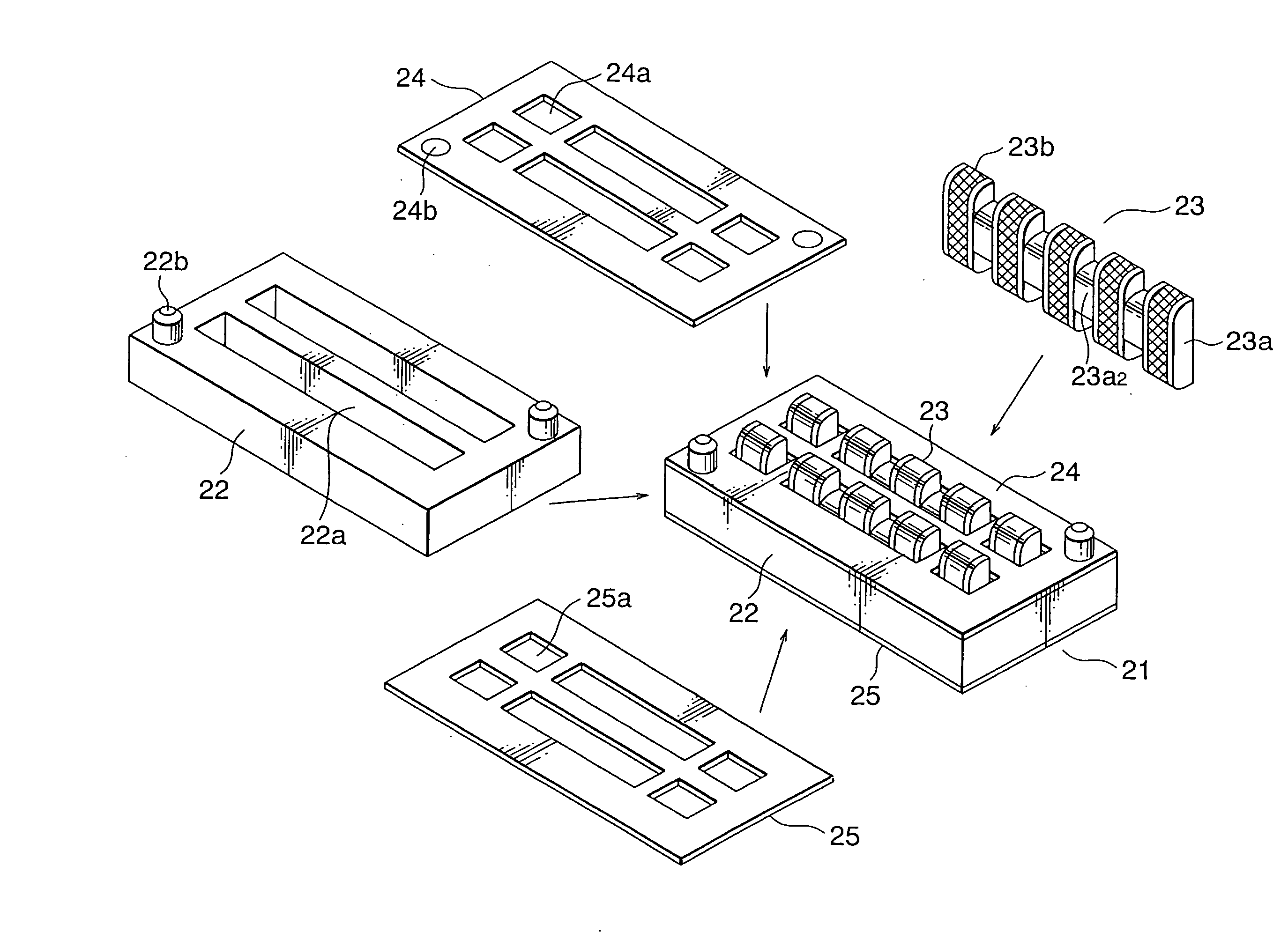
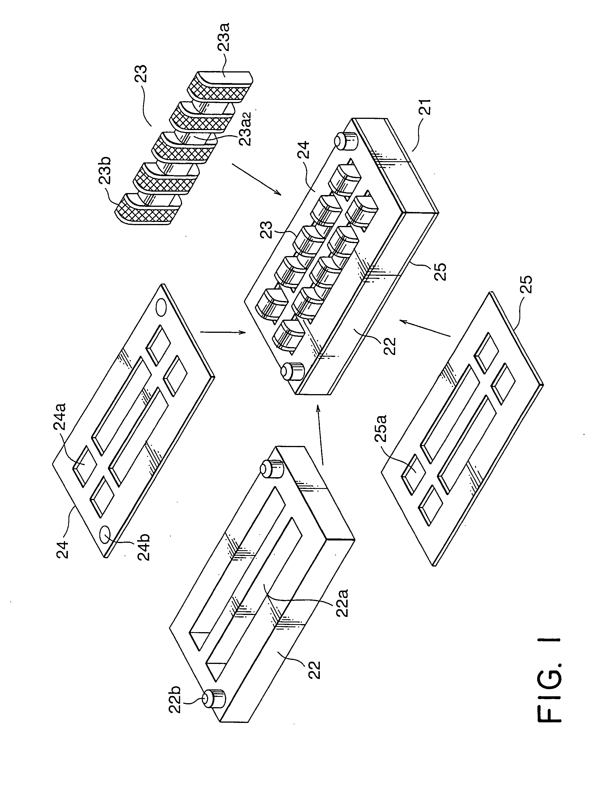
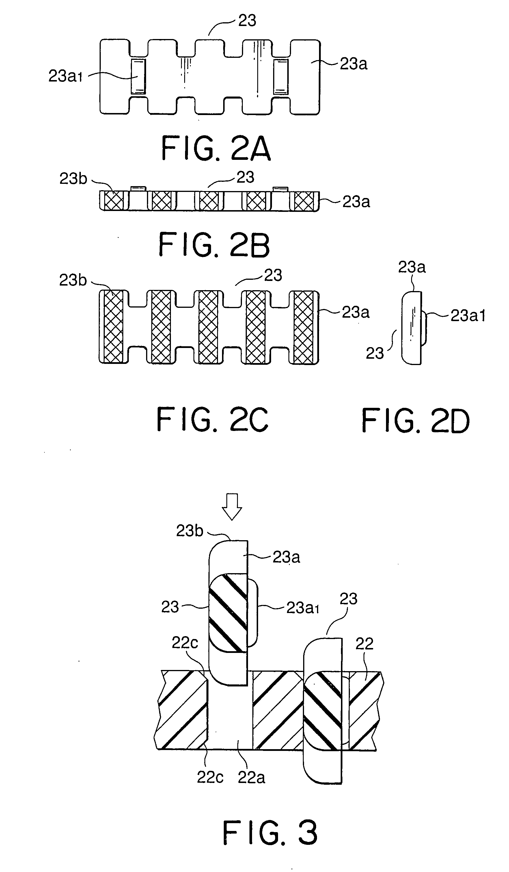
[0044]Referring to FIGS. 6 to 10, description will be made of a structure of a connector according to this invention.
[0045]The connector illustrated in the figure is a double-sided connector, i.e., a connector for double side connection. Specifically, the double-sided connector 1 illustrated in FIG. 6 comprises a plurality of, namely, two connection members 2 (FIGS. 9A and 9B) fitted to a frame 3 in parallel to each other. Each of the connection members 3 comprises a bone 2a as a strengthening member and an elastic member 2b formed around the bone 2a. On an outer surface of the elastic member 2b, an insulating sheet 2c is wound around. The insulating sheet 2c is fixed to the elastic member 2b, for example, by the use of an adhesive. The insulating sheet 2c is provided with a plurality of conductors 2d arranged at a predetermined pitch. Each of the conductors 2d is fixed to the insulating sheet 2c, for example, by the use of an adhesive. Thus, the connection member 2 is formed.
[0046]...
second embodiment
[0065]Next referring to FIG. 13, description will be made of a connector according to this invention. Similar parts are designated by like reference numerals and description thereof will be omitted.
[0066]In a connection member 2 illustrated in FIG. 13, a bone 2a is formed at positions corresponding to dowel portions 2b1. The dowel portions 2b1 are made of a material same as that of the bone 2a and integrally formed with the bone 2a. Thus, the structure of the connection member 2 may be modified in various manners.
[0067]With the above-mentioned connector also, similar merits to those of the connector described in connection with FIGS. 6 to 12 are expected.
third embodiment
[0068]Referring to FIG. 14, description will be made of a connector according to this invention. Similar parts are designated by like reference numerals and description thereof will be omitted.
[0069]In FIG. 14, a connection member 2′ comprises an elastic member 2b, an insulating sheet 2c, a plurality of conductors 2d, and a protruding portion 2e. A frame 3 has a pair of slits 3a each of which has a frame recess 3c formed at the center to serve as an engaged portion.
[0070]When the connection member 2′ is inserted into the slit 3a of the frame 3 in a first direction A1, the protruding portion 2e of the connection member 2′ is brought into contact with a slant surface 3b1. Thereafter, the protruding portion 2e is brought into contact with a flat portion 3b4 to be pushed leftward so that the elastic member 2b is deformed. When the connection member 2′ is further inserted, the protruding portion 2e is engaged with the frame recess 3c so that the elastic member 2b is recovered into an ori...
PUM
 Abstract
Description
Claims
Application Information
 - R&D
- Intellectual Property
- Life Sciences
- Materials
- Tech Scout
- Unparalleled Data Quality
- Higher Quality Content
- 60% Fewer Hallucinations
Browse by: Latest US Patents, China's latest patents, Technical Efficacy Thesaurus, Application Domain, Technology Topic, Popular Technical Reports.
© 2025 PatSnap. All rights reserved.Legal|Privacy policy|Modern Slavery Act Transparency Statement|Sitemap|About US| Contact US: help@patsnap.com


