Small size electrical connector assembly

Inactive Publication Date: 2007-10-04
HON HAI PRECISION IND CO LTD
View PDF29 Cites 37 Cited by
  • Summary
  • Abstract
  • Description
  • Claims
  • Application Information

AI Technical Summary

Benefits of technology

[0008] Accordingly, an object of the present invention is to provide an electrical connector asse

Problems solved by technology

When formed in 1990, the original goals were limited to define de facto mechanical envelopes within disk drives can be developed to fit compact computer and other small products.
However, such elongated latch member is hard to be actuated by the pulling member, otherwise the latch member must have enough thickness or made by high-quality material having enough rigidity to achieve the goal of latching reliably and unlatching easily.
Low profi

Method used


Image

  • Small size electrical connector assembly
  • Small size electrical connector assembly
  • Small size electrical connector assembly

Examples


Embodiment Construction

[0020] Reference will now be made to the drawing figures to describe the present invention in detail.

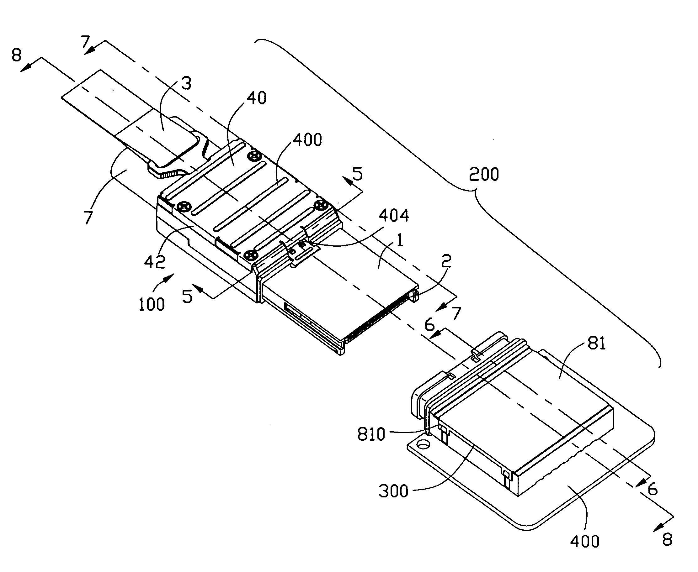
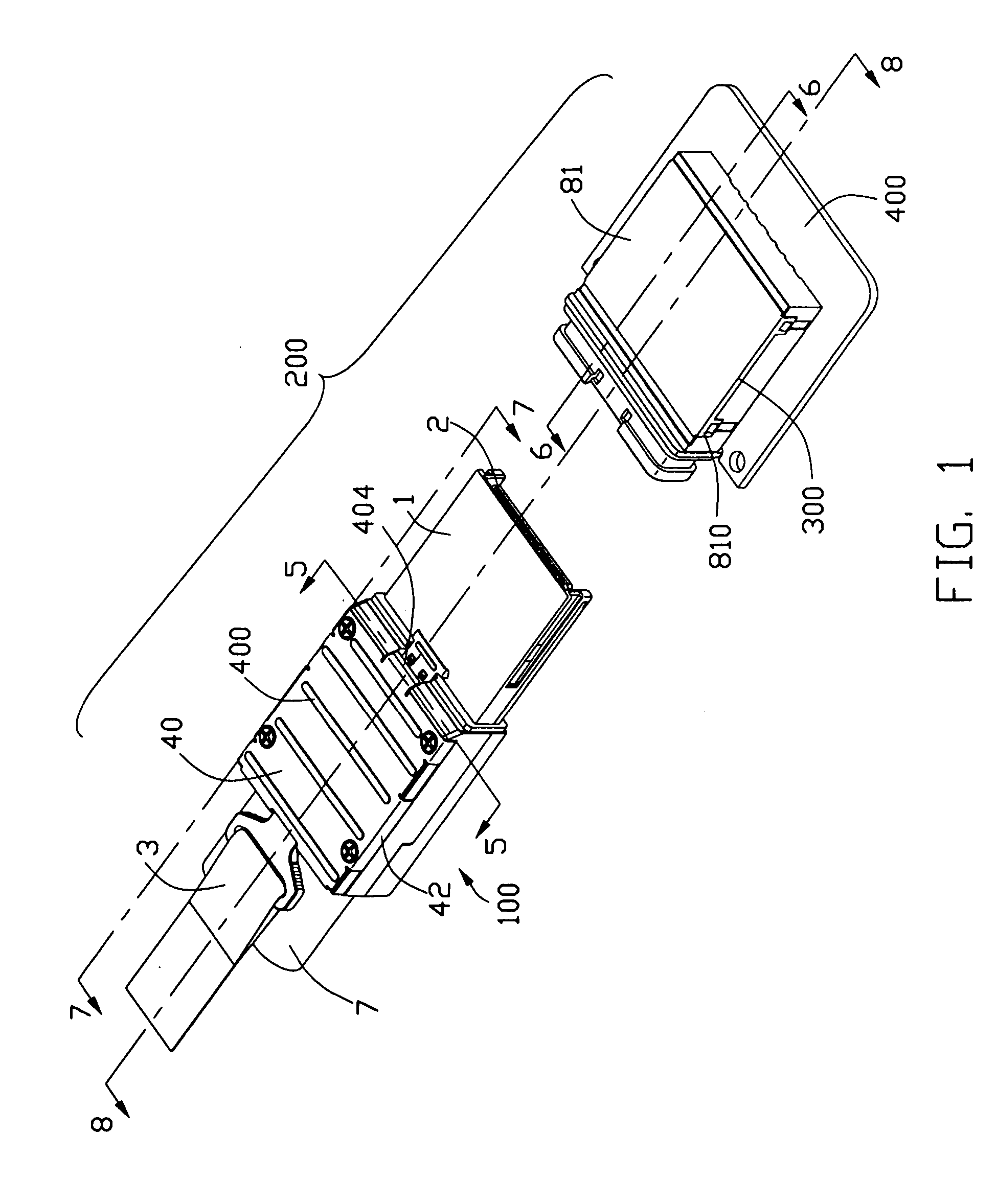
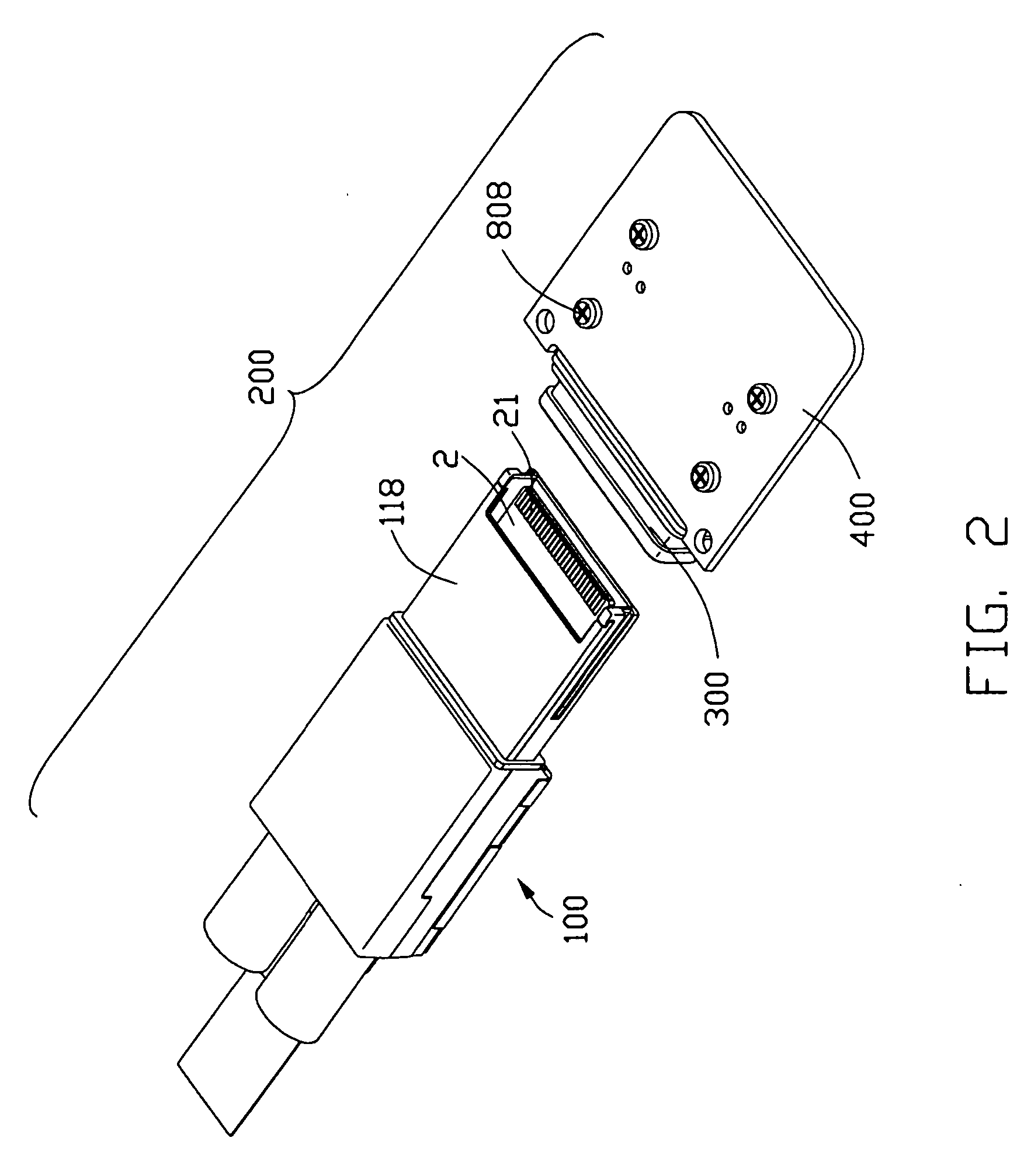
[0021] Referring to FIGS. 1-2, an electrical connector assembly 200 in accordance with the present invention comprises a plug connector 100 and a board connector 300 mounted on a planar circuit board 400 for mating with the plug connector 100.

[0022] Referring to FIGS. 3-4 in conjunction with FIGS. 5, 7-9, the plug connector 100 comprises a metal housing 1, a circuit card 2 located in the housing 1, a pair of cables 7 juxtaposed arranged to electrically connect with the circuit card 2, a latch mechanism 3 assembled to the housing 1, a metal shell 4 assembled to the housing 1 to partially cover the latch mechanism 3.

[0023] The housing 1 of the plug connector 100 is made of metal material and comprises a base 11, a cover 12 engagble with the base 11 and a receiving space 15 formed between the base and the cover 11, 12. Each base 11 and cover 12 comprises a rectangular base section 13...


PUM


Abstract

An electrical connector assembly (200) includes a plug connector (100) and a board connector (300). The board connector defines a frame (80) having a pair of holes (809) for receiving a pair of latches (3112) of a latch member (31) the plug connector, a hollow interior cavity (806) receiving part of housing (1) of the plug connector, and an insulative housing (90) supported a number of terminals (91) electrically connecting with conductive pads (21) of a circuit card (2) of the plug connector (100). The plug connector (100) includes a pulling member (32) cooperating with the latch member to actuate the latches of the latch member from separating from the holes of the board connector to disengage the board connector from the plug connector.

Description

CROSS-REFERENCE TO RELATED APPLICATIONS [0001] This application is related to U.S. patent application Ser. No. 11 / 201,521 filed on Aug. 11, 2005 and entitled “CABLE CONNECTOR ASSEMBLY WITH LATCHING MECHANISM”, U.S. patent application Ser. No. 11 / 201,461 filed on Aug. 11, 2005 and entitled “CABLE CONNECTOR ASSEMBLY WITH LATCHING MECHANISM”, U.S. patent application Ser. No. 11 / 268,906 filed on Nov. 8, 2005 and entitled “CABLE CONNECTOR ASSEMBLY WITH LATCHING MECHANISM”, U.S. patent application Ser. No. 11 / 268,902 filed on Nov. 8, 2005 and entitled “JUXTAPOSED CABLE CONNECTOR ASSEMBLIES”, and U.S. patent application Ser. No. 11 / 322,692filed on Dec. 30, 2005 and entitled “STACKED CONNECTOR ASSEMBLY”, U.S. patent application Ser. No. 11 / 213,048 filed on Aug. 26, 2005 and entitled “CABLE CONNECTOR ASSEMBLY WITH EMI GASKET”, and the copending U.S. patent application entitled “CABLE CONNECTOR ASSEMBLY WITH LATCHING MECHANISM”, all of which have the same applicant and assignee as the present...

Claims


Application Information

Patent Timeline
IPC IPC(8): H01R13/627H01R12/71
CPCH01R13/6335H01R13/6275
Inventor WU, JERRY
Owner HON HAI PRECISION IND CO LTD
Why Eureka
Try Eureka