Supercharge Your Innovation With Domain-Expert AI Agents!

Electrical terminal connector and method of fabricating the same

a technology of electrical terminals and connectors, which is applied in the direction of coupling device connections, coupling device details, and relieving strain on wire connections, etc., can solve the problems of difficult fabrication, complicated structure of conducting elements b>50/b>d, and inconvenient overall assembly of connectors, etc., to achieve better combination, better structural strength, and better combination

Inactive Publication Date: 2007-10-04
KS TERMINALS INC
View PDF5 Cites 2 Cited by
  • Summary
  • Abstract
  • Description
  • Claims
  • Application Information

AI Technical Summary

Benefits of technology

"The present invention provides an improved electrical terminal connector that solves problems of prior art. It includes an angled insulating housing, a conducting terminal, and a deformable cylindrical crimp ferrule. The insulating housing has a window and a cover that can be opened and closed. The crimped portion of the conducting terminal has an elongation with an axial slit to tolerate radial deformation. The crimping end of the cylindrical crimp ferrule has a diameter slightly larger than that of the conducting terminal. The invention has better combination between the conducting terminals, internal conducting elements, and structural strength. It also has easier assembly and improved insertion of external wire."

Problems solved by technology

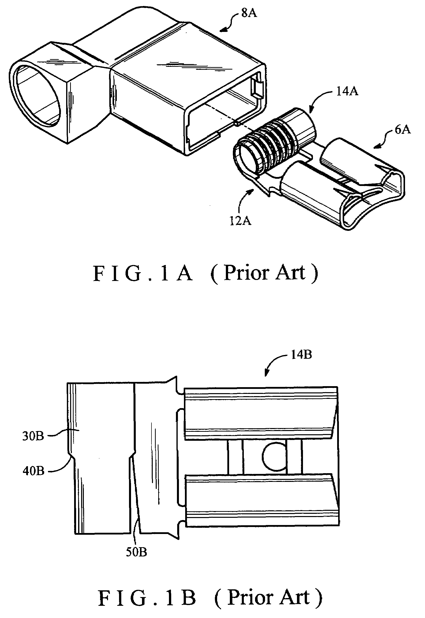
Meanwhile, the conducting element 6A sticks out and inserts into the insulating housing 8A by an inverting hook 12A; consequently, it is inconvenient for the overall assembly of the connector.
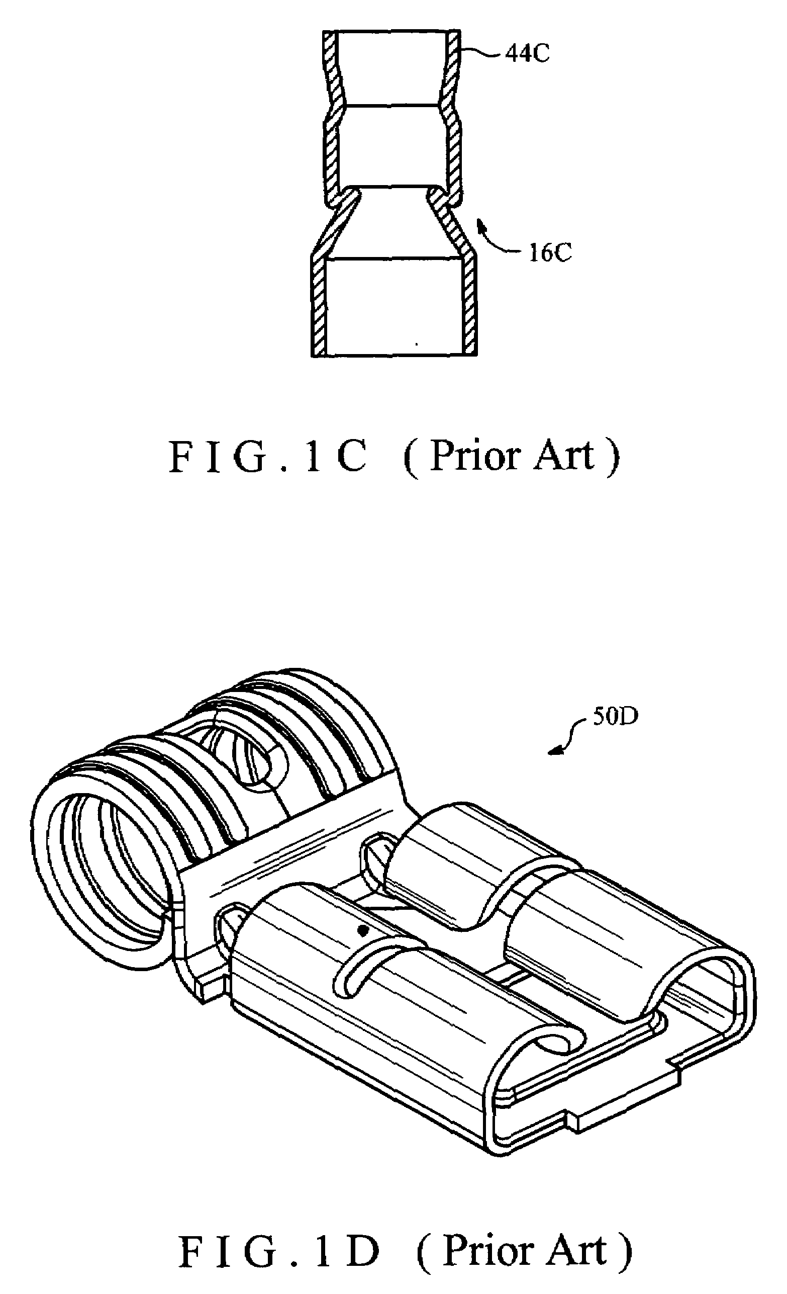
In order to connect the conducting core without any additional cylindrical crimp ferrule, the structure of the conducting element 50D is very complicated and not easy to fabricate.

Method used


Image

  • Electrical terminal connector and method of fabricating the same
  • Electrical terminal connector and method of fabricating the same
  • Electrical terminal connector and method of fabricating the same

Examples


Embodiment Construction

[0024]The present invention discloses an electrical terminal connector, wherein some of the basic electrical wire elements and insulating principles are described in the prior art, and therefore will not be described in detail below. Simultaneously, the drawings shown in this specification express the characteristics of this invention without actual dimensions.

[0025]The electrical terminal connector of this invention includes an angled insulating housing 2. Inside the insulating housing 2, there are a conducting terminal 3 and a deformable cylindrical crimp ferrule 4 to be assembled to each other.

[0026]Referring to FIGS. 2A and 2B, the preferred embodiment of the insulating housing 2 of this invention is shown.

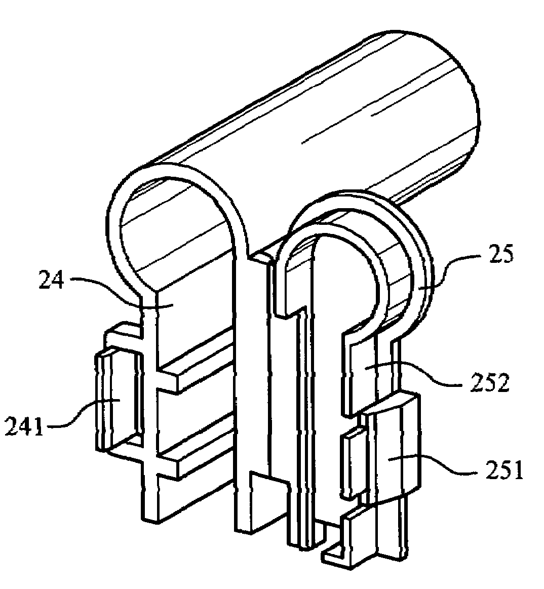
[0027]As shown in FIG. 2A, the insulating housing 2 has an angled structure 24. Two ends of the angled structure 24 are a first opening 21 and a second opening 22. Additionally, there is a through passage therein the insulated housing 2.

[0028]Referring to FIG. 2B, in a preferr...


PUM

PropertyMeasurementUnit
cylindrical shapeaaaaaaaaaa
elongationaaaaaaaaaa
diameteraaaaaaaaaa

Abstract

An electrical terminal connector and method of fabricating the same is provided. The electrical terminal connector includes an angled insulating housing, a conducting terminal and a cylindrical crimp ferrule positioned therein. Two ends of the insulating housing have a first opening and a second opening, while the angled insulating housing has a through passage therein. The conducting terminal includes a flat-ended connecting portion facing the first opening and a crimped-ended facing the second opening. The cylindrical crimp ferrule has a core-connecting end facing the second opening and a crimped portion facing the crimping end of the conducting terminal. The angled insulating housing further includes a window with a cover at the sidewall near the first opening. One end of the covers pivots at the side of the window, while the other end of the cover comprises a fastening means. The fastening means can be operationally fastened to the matching means forming an opening position and a closed position. The crimped portion of the conducting terminal extends towards the second opening with an elongation. The elongation comprises an axial slit to tolerate radial deformation. The crimping end of the cylindrical crimp ferrule has a diameter slightly larger than that of the extended length at the crimped portion.

Description

BACKGROUND OF THE INVENTION[0001]Referring to FIG. 1A, the prior art U.S. Pat. No. 4,298,243 shows an electrical connector for connecting two kinds of electrical conducting terminals. There is only one conducting element 6A located inside the insulating housing 8A. The conducting element 6A connects a flat-type conducting terminal to a conducting core. Wherein the conducting core is directly inserted into the cylindrical crimp ferrule 14A at the end of the conducting element 6A. An external clamping force is then exerted to deform the cylindrical crimp ferrule 14A to fasten the conducting core; therefore, the connecting force between the conducting core and the conducting element 6A is weak. Meanwhile, the conducting element 6A sticks out and inserts into the insulating housing 8A by an inverting hook 12A; consequently, it is inconvenient for the overall assembly of the connector.[0002]Referring to FIGS. 1B and 1C, another example of the prior art shown in U.S. Pat. No. 5,203,726 is...

Claims


Application Information

Patent Timeline
Patent Type & Authority Applications(United States)
IPC IPC(8): H01R13/60H01R13/58
CPCH01R4/20H01R13/115H01R13/501H01R43/20Y10T29/49204Y10T29/49183Y10T29/49151Y10T29/4994Y10T29/49911Y10T29/49174
Inventor LU, YUAN-FENG
Owner KS TERMINALS INC
Features
  • R&D
  • Intellectual Property
  • Life Sciences
  • Materials
  • Tech Scout
  • Unparalleled Data Quality
  • Higher Quality Content
  • 60% Fewer Hallucinations
Learn More