Flexible endoscope with variable stiffness shaft

a flexible, endoscope technology, applied in the field of endoscopes, can solve the problem that the shaft made in this way can be expensive to manufactur

Inactive Publication Date: 2007-10-04
BOSTON SCI SCIMED INC
View PDF16 Cites 111 Cited by
  • Summary
  • Abstract
  • Description
  • Claims
  • Application Information

AI Technical Summary

Benefits of technology

[0006]As will be described in further detail below, the present invention is a shaft for use in a med

Problems solved by technology

While both approaches work, shafts made in

Method used


Image

  • Flexible endoscope with variable stiffness shaft
  • Flexible endoscope with variable stiffness shaft
  • Flexible endoscope with variable stiffness shaft

Examples


Embodiment Construction

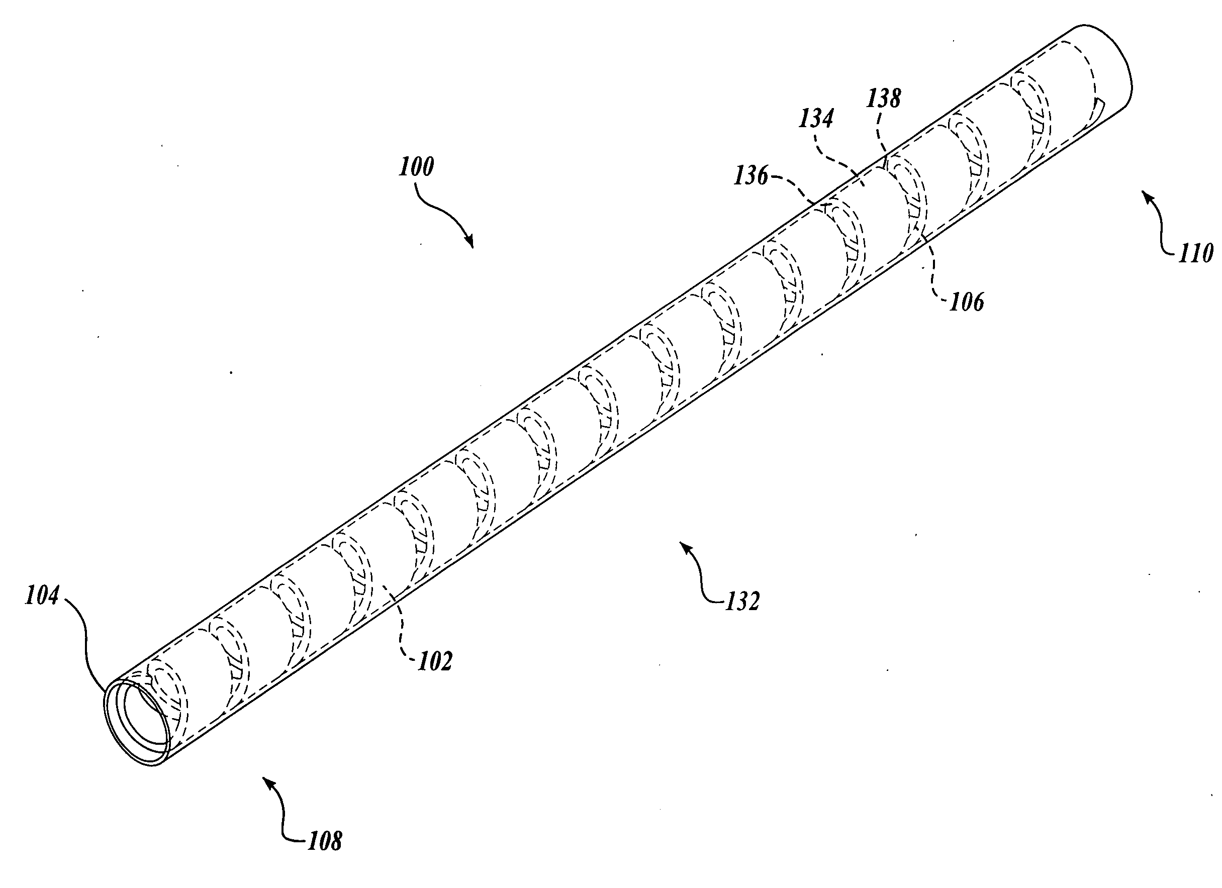
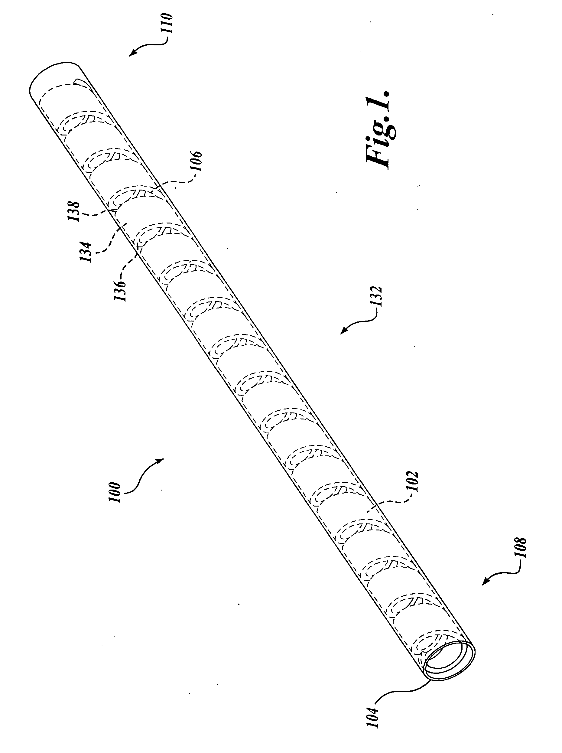
[0022]As indicated above, embodiments in accordance with the present invention are related to methods and shafts for use in a medical device having a flexibility that can vary along its length. In the embodiments disclosed, the shaft is used in an endoscope. However, it will be appreciated that the present invention can also be used in catheters or other minimally invasive devices. In a co-pending application titled “Flexible Device Shaft with Angled Spiral Wrap,” Attorney Docket No. BSEN126408, applicant describes a flexible spiral wrap having wraps with angled, multi-planar, arcuate and irregular surface edges, which also are used to adjust shaft flexibility. This application is incorporated herein expressly by reference.

[0023]FIG. 1 is an illustration of a portion of a shaft 100 having a flexibility that varies along the length of the shaft. In one embodiment, the shaft is constructed as a spiral wrap 102 that is overlaid with a sheath including a polyurethane wrapper (not shown)...


PUM


Abstract

A shaft for a medical device includes an outer sheath and a flexible spiral wrap therein. The flexibility of the spiral wrap is modified by changing the width of the wraps of a spiral, the thickness of the wraps of a spiral, or the gap spacing of the spiral. The spacing between wraps is maintained by attaching the spiral wrap to the cover sheath that surrounds the spiral wrap at two or more locations.

Description

FIELD OF THE INVENTION[0001]The present invention relates to medical devices in general, and to endoscopes in particular.BACKGROUND OF THE INVENTION[0002]As an alternative to performing more invasive medical procedures, many physicians are utilizing endoscopes and catheters to perform diagnostic and therapeutic procedures on internal tissues of patients. With this less invasive approach, a medical device such as an endoscope or catheter is advanced to a site of interest and the procedure is performed. Most endoscopes and some catheters comprise a steerable shaft that is advanced through the patient's anatomy until the distal tip reaches the point of interest.[0003]To withstand the forces required to advance the endoscope through the anatomy while allowing the device to be steered, some endoscopes and catheters have a variable stiffness along their shafts. The tip of the device is generally made flexible to allow it to be steered, while the proximal end is stiffer to transmit the for...

Claims


Application Information

Patent Timeline
IPC IPC(8): A61M25/00
CPCA61B1/00071A61M25/0054A61B1/0055A61B1/005
Inventor MACNAMARA, FRANCIS T.DAYTON, PETER L.CASTRO, IANMASEDA, LUIS J.SBARDELLI, JOHNZOCCHI, MICHAEL R.HARRIS, EDWARD M.BOULAIS, DENNIS R.BANIK, MICHAEL S.CHIN, ALBERT C.C.
Owner BOSTON SCI SCIMED INC
Why Eureka
Try Eureka