Device for the dynamic fixation of bones

a dynamic fixation and bone technology, applied in the field of dynamic fixation of bones, can solve the problem of the head segment slipping to one side, and achieve the effects of reducing stress, improving strength and elasticity, and modifying damping properties and elastic behavior of ball joint-like connections

Inactive Publication Date: 2007-10-04
SYNTHES USA
View PDF12 Cites 199 Cited by
  • Summary
  • Abstract
  • Description
  • Claims
  • Application Information

AI Technical Summary

Benefits of technology

[0028] In a different embodiment, the intermediate element is produced from a visco-elastic material, such as a polycarbonate-urethane. Depending on the viscosity of this visco-elastic material, a more or less rapid reduction in the stresses, which have arisen in the connection during the locking of the ball joint, takes place over time in that the visco-elastic material, which is under pressure, can creep into the free spaces, the design of which is planned especially and which support the positive connection. With that, the advantage may be that, due to the decay of the internal stresses arising during the locking of the ball joint, the in situ creates positive connection gains in strength and elasticity.
[0029] If the intermediate element is built up at least partially from a visco-elastic material, it is possible to modify the damping properties and the elastic behavior of the ball joint-like connection by modifying the viscosity of the material. The higher the viscosity of the material, the more elastic is the behavior of the ball joint-like connection under normally occurring brief stresses, and the smaller is the damping component.
[0030] A more elastic behavior is ideal under normally occurring brief stresses and a more viscous behavior is ideal in the long run for decaying the internal stresses for optimally utilizing the flexibility of the material.

Problems solved by technology

It is a disadvantage of this known device that the head segment is clamped by friction between the elastic clamping elements, so that the head segment can slip to one side if the torque between the bone fixation agent and the longitudinal carrier is sufficiently high.

Method used


Image

  • Device for the dynamic fixation of bones
  • Device for the dynamic fixation of bones
  • Device for the dynamic fixation of bones

Examples


Embodiment Construction

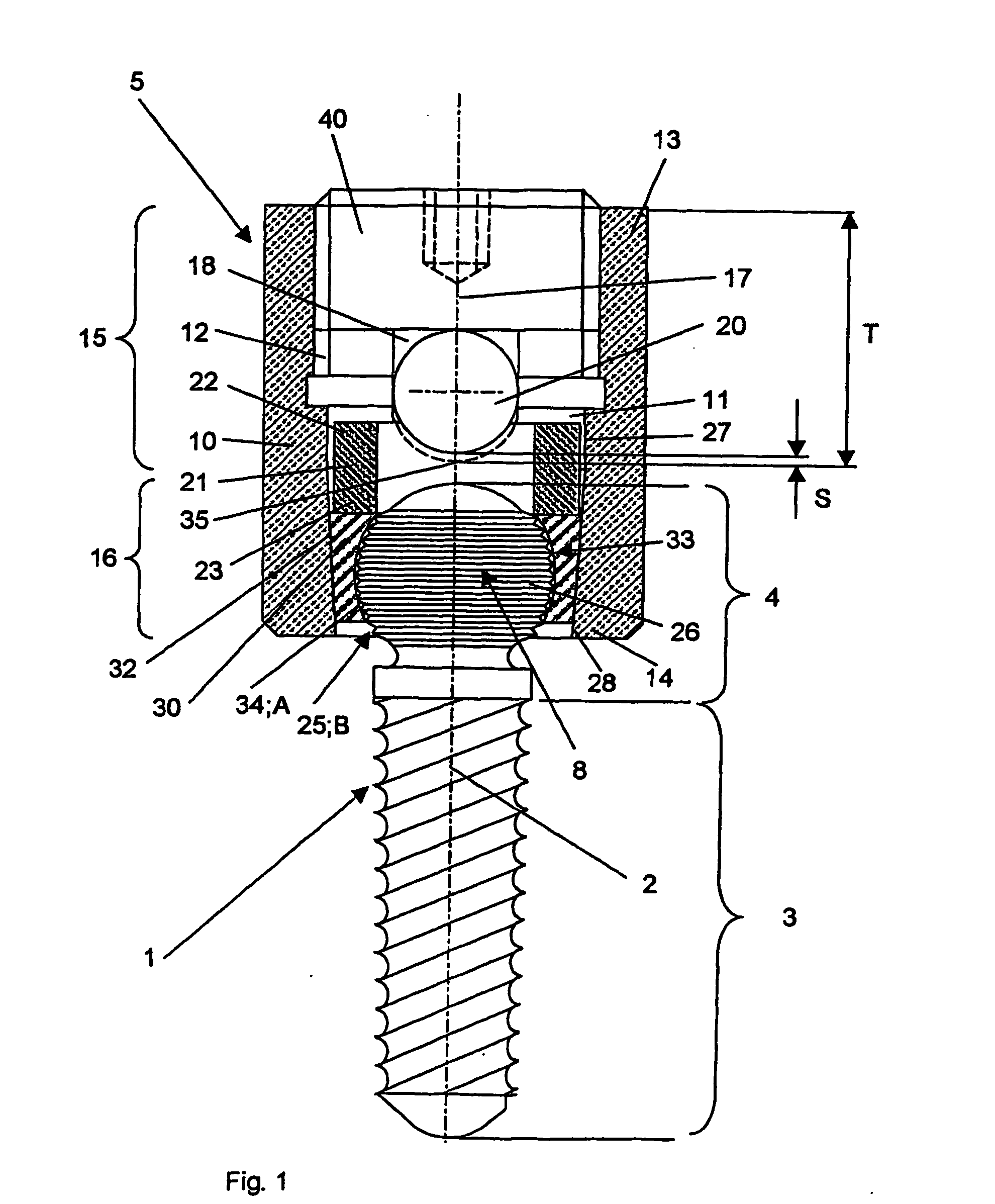
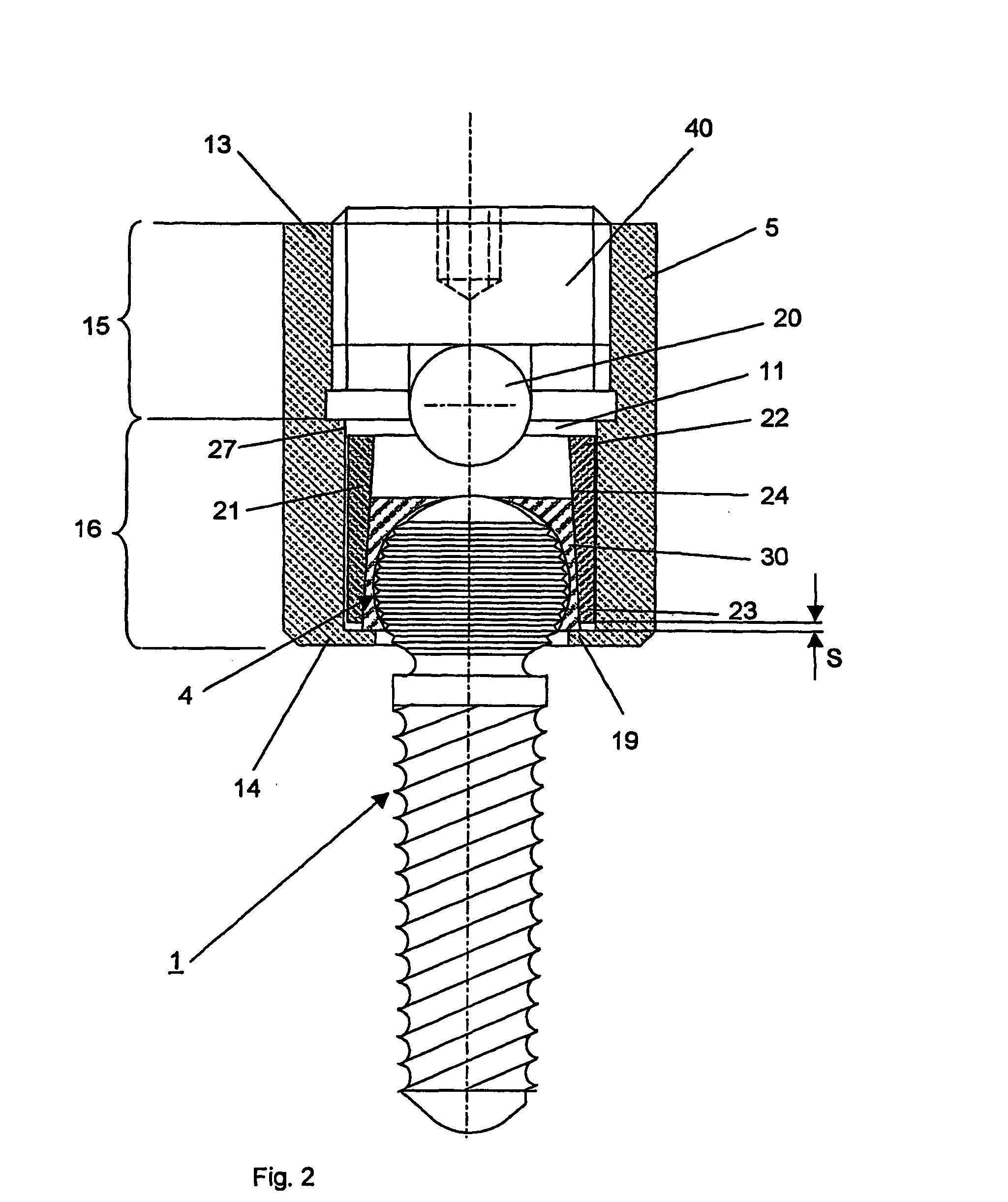
[0074]FIG. 1 shows an embodiment that includes a bone fixation agent 1 in the form of a pedicle screw having a central axis 2 and a connecting part 5 in the form of a tube 10 for connecting the bone fixation agent 1 with a longitudinal carrier 20. The bone fixation agent 1 has a coaxial anchoring segment 3, which is configured as the shaft of a screw. The fixation agent 1 also has a head segment 4, which is also disposed coaxially and adjoins the screw shaft at the top. Before it is fixed in the connecting part 5, the longitudinal carrier 20 is placed in a channel 18 disposed in the connecting piece 5 and subsequently fixed by means of the clamping means 40. The channel 18 passes through the connecting part 5 transversely to the central axis 2 and is open at the upper end 13 of the connecting part 5. The ball joint 8 is formed between the connecting part 5 and the bone fixation agent 1 by the intermediate element 30 and the head segment 4, the wall 34 of the cavity 33 in the interme...


PUM


Abstract

An intermediate element for a detachable, lockable, ball joint-like connection in a device for the dynamic fixation of bones has a longitudinal axis, an outer wall concentric with the longitudinal axis, and an inner wall forming a coaxial cavity. Either the outer wall or the inner wall comprises one of two contact zones that form the ball joint-like connection. The intermediate element is at least partly made of a super-elastic or visco-elastic material.

Description

CROSS-REFERENCE TO RELATED APPLICATION [0001] This is a continuation of pending International Application No. PCT / CH2004 / 000443, filed Jul. 12, 2004, the entire contents of which are expressly incorporated herein by reference thereto.FIELD OF THE INVENTION [0002] The invention relates to a device for the dynamic fixation of bones and, more particularly, to an intermediate element of the device for providing a detachable, lockable, ball joint-like connection. BACKGROUND OF THE INVENTION [0003] The present invention relates to a device for the dynamic stabilization of bones or bone fragments, especially of vertebrae, and comprises at least one longitudinal carrier, which is connected over at least two bone fixation agents attached to vertebral bodies. The bone fixation agents preferably are pedicle screws, which are brought from the rear through the pedicle into the vertebral bodies. [0004] The main indications for a dynamic fixation, especially for one passed through from the rear, a...

Claims


Application Information

Patent Timeline
Patent Type & Authority Applications(United States)
IPC IPC(8): A61F2/30A61B17/00A61B17/70A61B17/80A61B17/86
CPCA61B17/7032A61B17/7035A61B17/7037A61B2017/00867A61B17/8047A61B17/8695A61B2017/00862A61B17/7041
Inventor SCHLAPFER, FRIDOLIN
Owner SYNTHES USA
Why Eureka
Try Eureka