

Dynamic/static facet fixation device and method
- Summary
- Abstract
- Description
- Claims
- Application Information
AI Technical Summary
Benefits of technology
Problems solved by technology
Method used
Image

Examples
Embodiment Construction
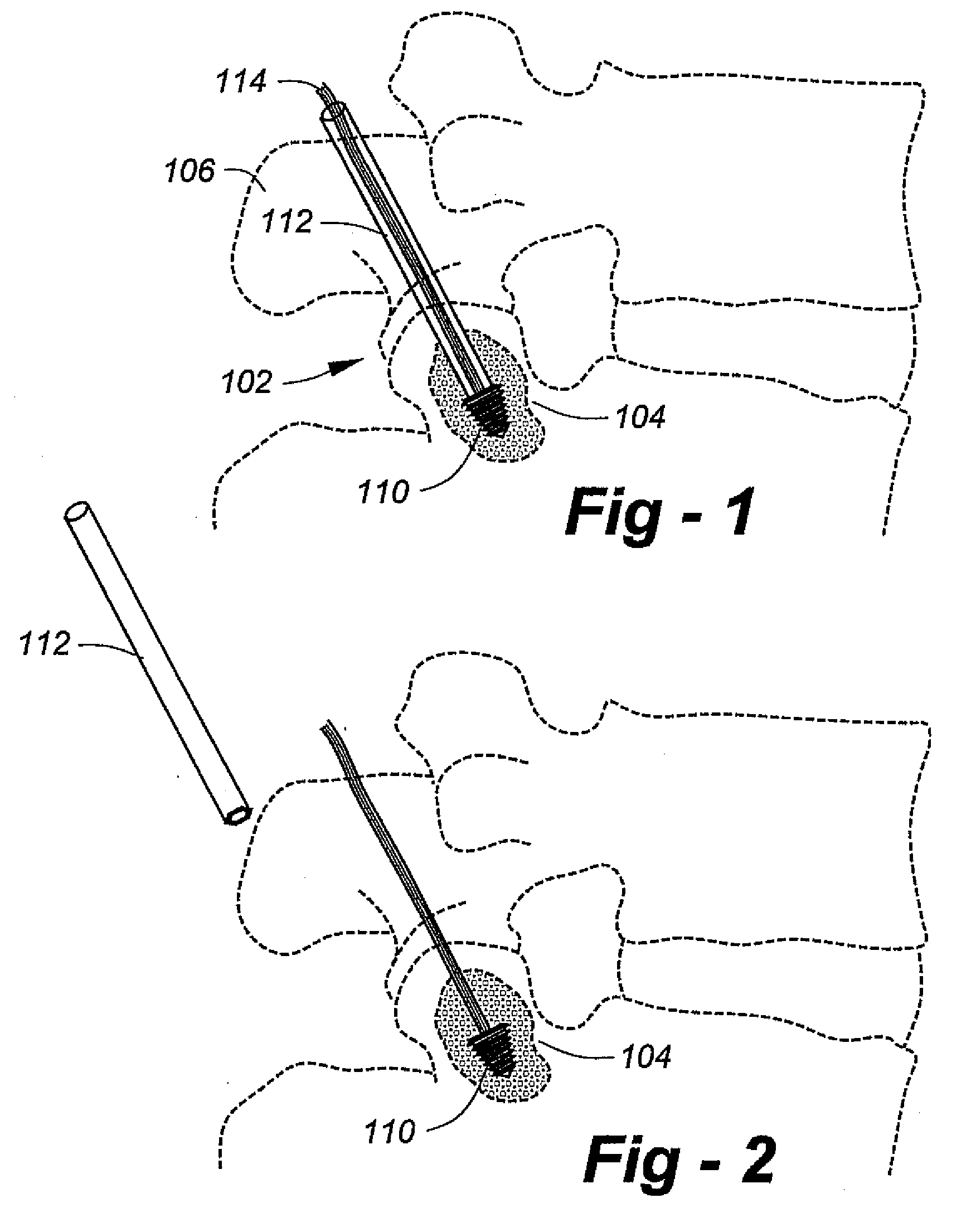
[0015]FIG. 1 is a drawing which shows an initial procedure according to the invention for the introduction of a dynamic facet stabilization system. Using a non-translaminar approach, a screw 110, preferably conical in shape, is placed perpendicular to the facet joint surface and advanced into intra-pedicle bone 104. An elastic cord (i.e., surgi-cord, “bungee” cord) 114 is attached to the screw 110. The facet joint is indicated generally at 102. Item 106 is the spinous process for the upper vertebral body. Item 112 is an introduction tool that is removed after placement of the anchor screw, as shown in FIG. 2.
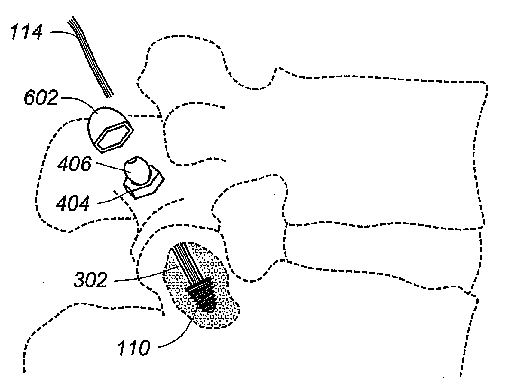
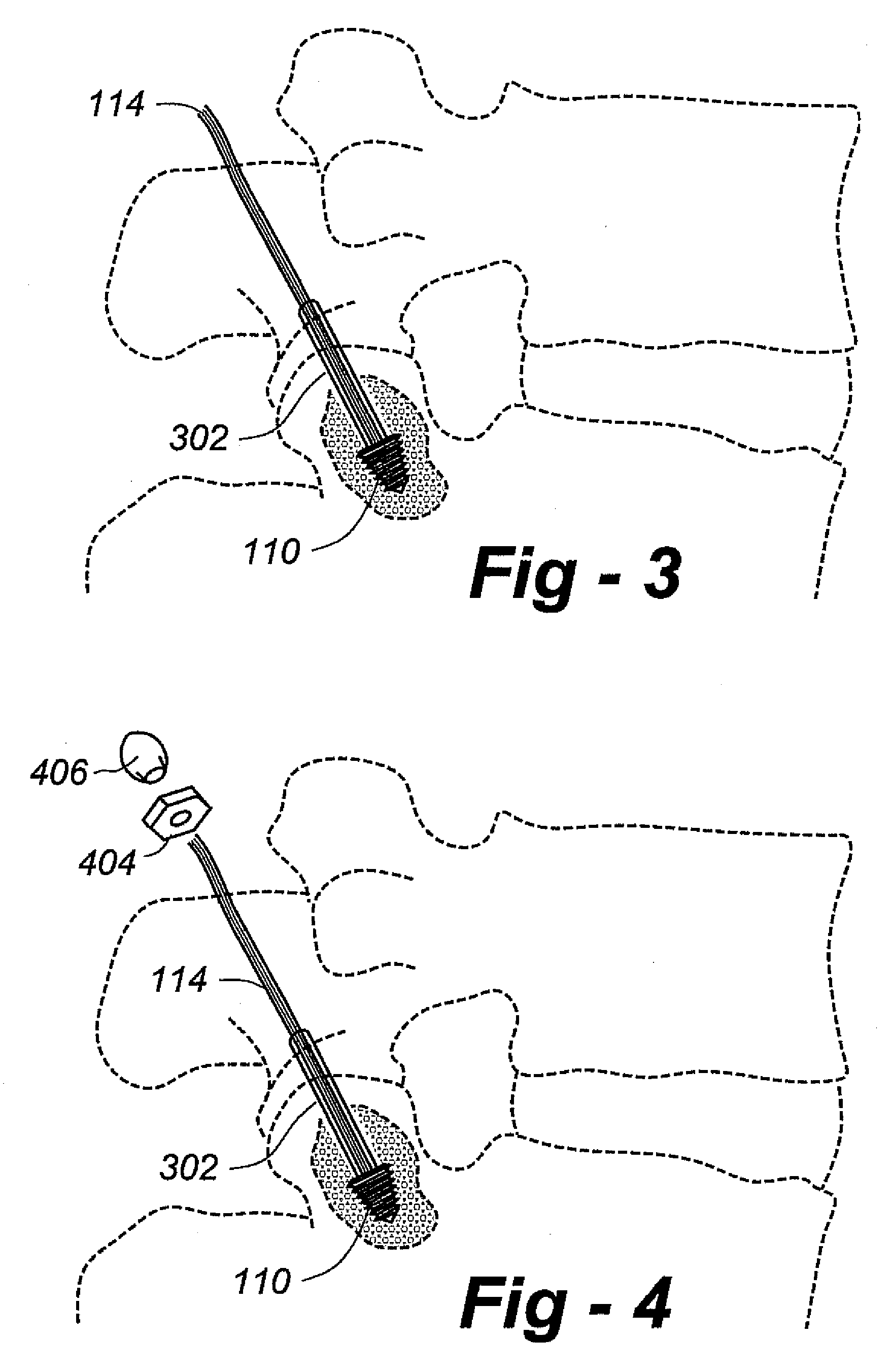
[0016]Turning now to FIG. 3, to limit extension, an optional gliding sleeve 302 made of silicone or other material is placed over the cord 114 and advanced across the facet joint to the anchor screw. Following this procedure, a bottom anchor nut 404 and fenestrated grommet 406 are dressed over the cord 114. The placement is shown in FIG. 5, at which time the cord 114 is tensione...
PUM
 Abstract
Description
Claims
Application Information