
Dynamic/static facet fixation device and method

a dynamic/static fixation and facet technology, applied in the field of spinal stabilization, can solve the problems of system non-locking and limited to static fixation, and achieve the effect of dynamic or static stabilization and dynamic stabilization of the facet join

Inactive Publication Date: 2012-01-03
MEDICAL DESIGNS
View PDF6 Cites 4 Cited by
  • Summary
  • Abstract
  • Description
  • Claims
  • Application Information

AI Technical Summary

Benefits of technology

"This patent describes a system for stabilizing a facet joint in the spine using two anchor components that are implanted through the facet joint and into the bone marrow canal. A connector component connects the two anchor components and can be elastic or rigid, allowing for dynamic or static stabilization of the facet joint. The system has few exposed components, making it minimally invasive and efficient."

Problems solved by technology

Although open or micro techniques may be used, the system is non-locking and limited to static fixation.

Method used


Image

  • Dynamic/static facet fixation device and method
  • Dynamic/static facet fixation device and method
  • Dynamic/static facet fixation device and method

Examples


Embodiment Construction

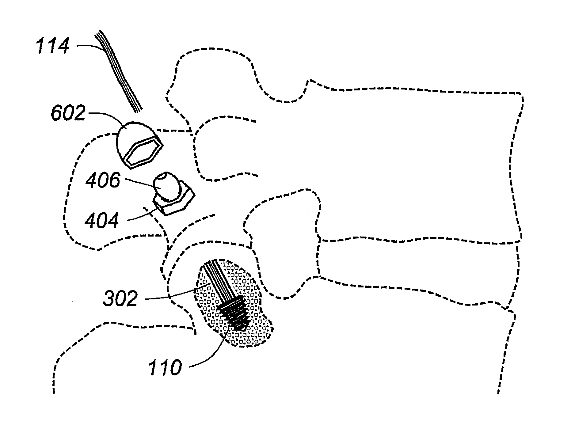
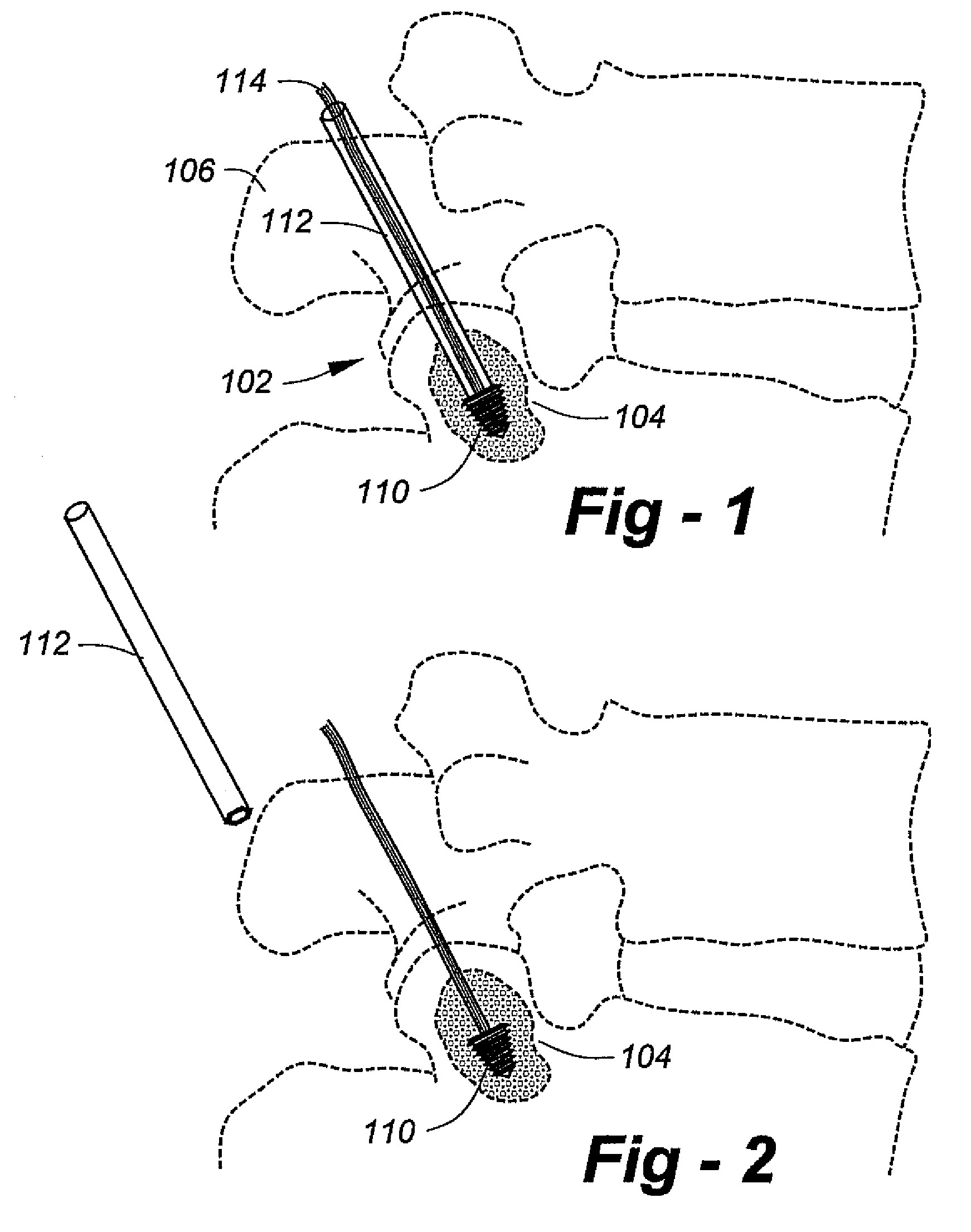
[0015]FIG. 1 is a drawing which shows an initial procedure according to the invention for the introduction of a dynamic facet stabilization system. Using a non-translaminar approach, a screw 110, preferably conical in shape, is placed perpendicular to the facet joint surface and advanced into intra-pedicle bone 104. An elastic cord (i.e., surgi-cord, “bungee” cord) 114 is attached to the screw 110. The facet joint is indicated generally at 102. Item 106 is the spinous process for the upper vertebral body. Item 112 is an introduction tool that is removed after placement of the anchor screw, as shown in FIG. 2.

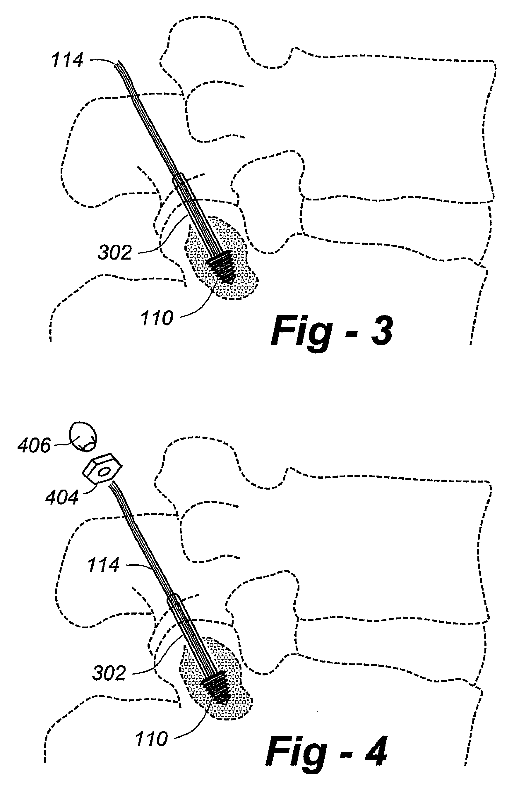
[0016]Turning now to FIG. 3, to limit extension, an optional gliding sleeve 302 made of silicone or other material is placed over the cord 114 and advanced across the facet joint to the anchor screw. Following this procedure, a bottom anchor nut 404 and fenestrated grommet 406 are dressed over the cord 114. The placement is shown in FIG. 5, at which time the cord 114 is tensione...


PUM


Abstract

A facet fixation system facilitates dynamic or static stabilization with few exposed components. A first anchor component is adapted for implantation through a facet joint and into intra-pedicle bone, and a second anchor component is adapted for fixation to the outer surface of the facet joint. A connector component connects the first and second anchor components. The connector component may be at least partially elastic, facilitating a dynamic stabilization of a facet joint, or rigid, facilitating a static stabilization of a facet joint.

Description

REFERENCE TO RELATED APPLICATION[0001]This application claims priority from U.S. Provisional Patent Application Ser. No. 60 / 776,451, filed on Feb. 24, 2006, the entire content of which is incorporated herein by reference.FIELD OF THE INVENTION[0002]This invention relates generally to spinal stabilization and, in particular, to a spinal implant placed across a facet joint via opener microsurgical techniques that allows for either dynamic (motion preserving) or static (no motion) stabilization.BACKGROUND OF THE INVENTION[0003]Various facet fixation techniques are known to those of skill in the art. The universal cannulated screw system of Medtronics includes a translaminar cannulated screw that is placed by guide wire across the facet joint from an entry point at the spinous process / laminate junction. This is opposite the actual facet joint, closing through the lamina and facet joint proper. The system provides only for static stabilization using a translaminar, open approach, with si...

Claims


Application Information

Patent Timeline
Patent Type & Authority Patents(United States)
IPC IPC(8): A61B17/70
CPCA61B17/7064
Inventor FALAHEE, MARK H.
Owner MEDICAL DESIGNS
Learn More