Wave electric power system

A technology of wave power generation and sliding vane, which is applied in ocean energy power generation, engine components, machines/engines, etc., can solve the unreported hydraulic transmission wave power generation system, affect the practicality and industrialization of wave power generation, and the engineering feasibility of wave power generation To achieve the effect of enhancing the ability to resist sea wind and wave damage, long trouble-free service life, and superior seawater corrosion

Inactive Publication Date: 2012-04-04
TAIHE WAVE ENERGY RES CENT QINGDAO ECONOMIC TECH DEV ZONE
View PDF24 Cites 13 Cited by
  • Summary
  • Abstract
  • Description
  • Claims
  • Application Information

AI Technical Summary

Problems solved by technology

The reason is that the real obstacle to the practical application of wave power generation is actually the poor engineering feasibility.
Although many schemes are perfect in theory, they are not feasible in engineering, and although some schemes are feasible, they are very difficult to implement in engineering
Since the 1970s, due to the energy crisis, the United Kingdom, Japan, Norway and other countries have invested a lot of manpower and material resources in the research of wave power generation. Shelved, affecting the practical and industrialization of wave power generation (see "Power Generation Equipment" 2007 No. 6 P508)
[0009] There are USP4105368, DEA2921381, etc. that use a buoy combined with a hydraulic mechanism as an energy conversion device, while CN1199822A, CN100501153C and CN101012803A all disclose the use of a buoy combined with a hydraulic transmission in their wave power generation system, but the use of special-shaped discs has not been reported in the prior art. A hydraulic transmission wave power generation system designed with a pontoon combined with a corrosion-resistant sliding vane connecting rod

Method used


Image

  • Wave electric power system
  • Wave electric power system
  • Wave electric power system

Examples


Embodiment Construction

[0029] Please refer to the following detailed description of a preferred embodiment of the present invention and accompanying drawings to further understand the technical content of the present invention and its purpose and efficacy.

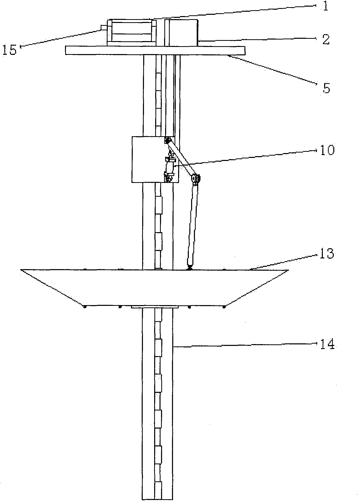
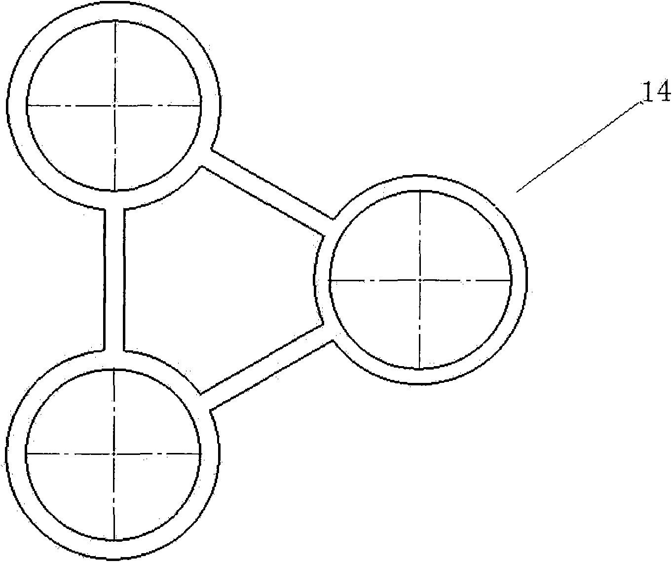
[0030] see figure 1 and figure 2 The lattice column type wave power generation system provided by the present invention has a working platform 5, which is used to place various devices such as the lifting mechanism 15, the hydraulic motor 2, and the generator 1; a control platform is arranged below the working platform 5 8. There is a hydraulic cylinder 10 on it, and the small platform is connected to the special-shaped dish-shaped buoy 13 at the lower part through the corrosion-resistant sliding piece connecting the pull rods 9 and 11; The disc buoy runs smoothly up and down. The special-shaped dish-shaped buoy moves up and down with the help of waves, and connects the pull rods 9 and 11 through corrosion-resistant slides to drive the hydrau...


PUM


Abstract

The invention discloses a pontoon-hydraulic lattice column type wave electric power system connected with a corrosion-resistant slip sheet linkage mechanism. The wave electric power system is characterized in that: a main fixed pile 14 consists of N (N is more than or equal to 3) subpiles which are arranged in a lattice column mode; a primary transduction system consists of a special disk-shaped pontoon 13 which is connected with the linkage mechanism and sleeved on the linkage mechanism, a hydraulic transmission mechanism and a control mechanism; wherein the linkage mechanism consists of slip sheets which are made of materials such as seawater corrosion-resistant resin and the like, a connecting rod fixing base 12, a buffer rope and connecting rods (9 and 11); the hydraulic transmission mechanism consists of a hydraulic motor 2, an oil tank 4, N( N is more than or equal to 3) hydraulic cylinders 10 and hydraulic oil pipes (3, 6 and 7); the control mechanism consists of a lifting mechanism 15 and a control platform 8; a second transduction system consists of a generator 1 on a working platform 5 and converts mechanism energy into electric energy. The wave electric power system has the advantage of high conversion efficiency, facilitates project implementation and has high seawater corrosion resistance and high capacity of resisting damage of wind and wave.

Description

technical field [0001] The invention relates to a system for generating electricity by using ocean waves, in particular to a high-efficiency buoy-hydraulic column wave power generation system which is easy to implement and capable of resisting seawater erosion and wind and wave damage. Background technique [0002] Under the gravitational force of celestial bodies such as the sun and the moon, seawater will produce periodic movements. Usually, the movement of seawater in the vertical direction is called tide, and the movement of seawater in the horizontal direction is called tidal current. The wind on the ocean can also cause the movement of sea water, commonly known as sea waves or waves, but wave energy is also one of the most unstable energy sources in ocean energy. At present, the system that utilizes the energy of seawater motion to generate electricity mainly uses tides, tidal currents and waves to drive generators to generate electricity. For example, CN1243911C propo...

Claims


Application Information

Patent Timeline
Patent Type & Authority Applications(China)
IPC IPC(8): F03B13/22
CPCY02E10/38Y02E10/30
Inventor 孙明刚
Owner TAIHE WAVE ENERGY RES CENT QINGDAO ECONOMIC TECH DEV ZONE
Why Eureka
Try Eureka