Method for detecting switching failure

a switching failure and detection method technology, applied in error detection/correction, instruments, computing, etc., can solve problems such as affecting work efficiency and system stability, engineers will not be able to determine problems, and achieve the effects of enhancing system stability, avoiding continuous system crash, and increasing fault analysis and fault solving abilities

Inactive Publication Date: 2007-10-04
INVENTEC CORP
View PDF5 Cites 40 Cited by
  • Summary
  • Abstract
  • Description
  • Claims
  • Application Information

AI Technical Summary

Benefits of technology

[0008] In the light of forgoing drawbacks, an objective of the present invention is to provide a method for detecting a switching failure applicable to the two fault resilient mechanisms FRB 2 and 3 defined under the IPMI architecture, such that continuous system crash can be avoided.
[0009] Another objective of the present invention is to provide a method for detecting a switching failure that records information about the failure of switching from the FRB 3 mechanism to the FRB 2 mechanism, providing users the ability to analyze and solve the failure.
[0010] Still another objective of the present invention is to provide a method for detecting a switching failure that achieves system stability with simple processes.
[0015] The method for detecting a switching failure of the present invention mainly solves the problem of failure to switch from FRB 3 to FRB 2 by establishing a failure record after a predetermined time has elapsed without the FRB 2 signal being generated and thereafter automatically rebooting the system. Thus, by the virtue of the present invention, the system stability is enhanced, fault-analysis and fault-solving abilities can be increased and continuous system crash can be avoided.

Problems solved by technology

However, when switching from the FRB 3 mechanism to the FRB 2 mechanism, there is a period during which a fault will not be detected, that is, when the FRB 3 mechanism is cancelled and the FRB 2 mechanism is entered, the FRB 2 mechanism has to carry out a memory detection command, if a system fault occurs during this period, it will not be recorded by the system, and there will be no response, such that the system has to be restarted.
In addition, an engineer will not be able to determine the problem and make maintenance accordingly.
However, a fault is generated based on the condition of software and hardware in cooperation at that instance, it will not occur every time the FRB 3 mechanism is switched to the FRB 2 mechanism.
Such uncertainty affects work efficiency and system stability.

Method used


Image

  • Method for detecting switching failure
  • Method for detecting switching failure
  • Method for detecting switching failure

Examples


Embodiment Construction

[0019] The present invention is described by the following specific embodiments. Those with ordinary skills in the arts can readily understand the other advantages and functions of the present invention after reading the disclosure of this specification. The present invention can also be implemented with different embodiments. Various details described in this specification can be modified based on different viewpoints and applications without departing from the scope of the present invention.

[0020] It should be noted that the appended drawings are simplified to schematically illustrate the basic structure of the present invention. Thus, only those elements pertaining to the present invention are shown; the actual layout may be more complicated.

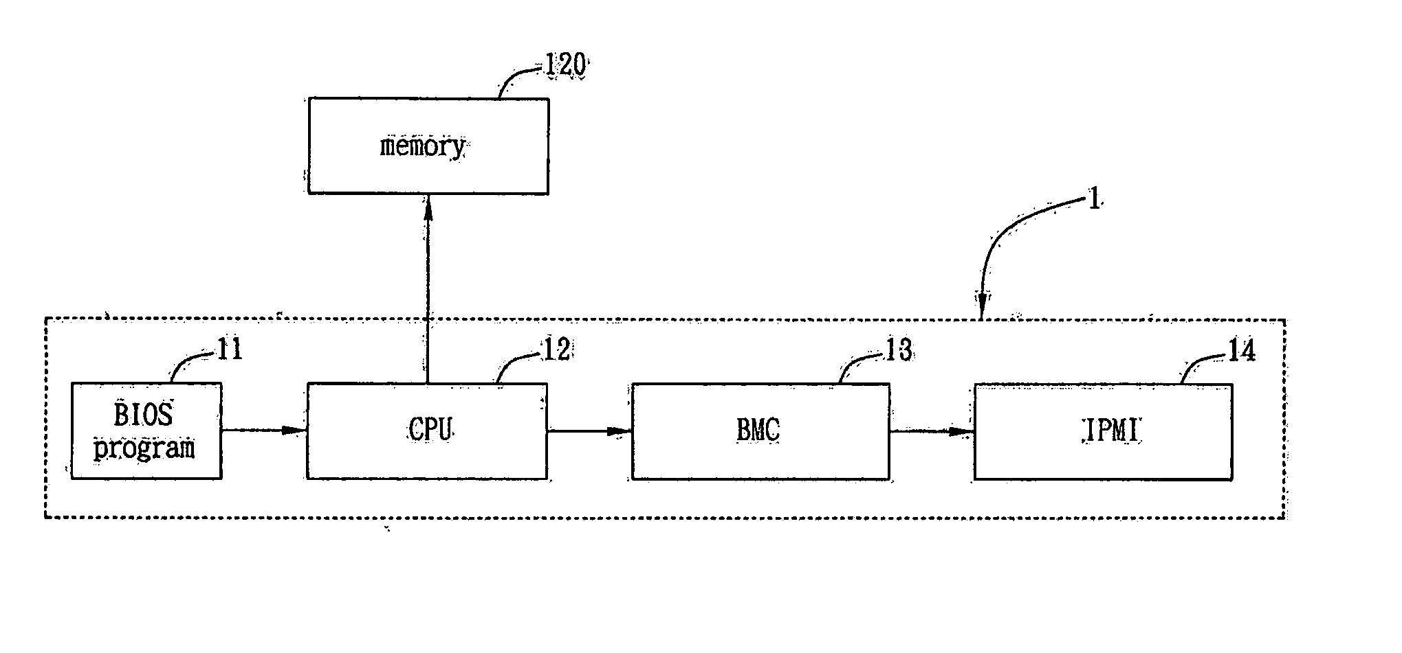
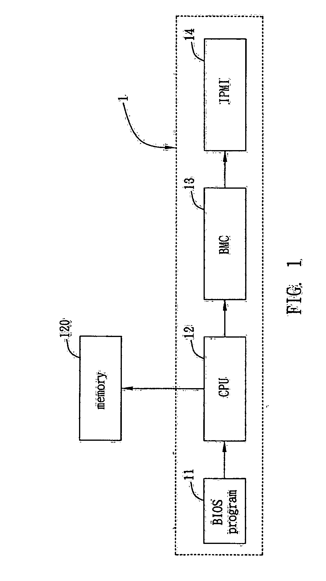
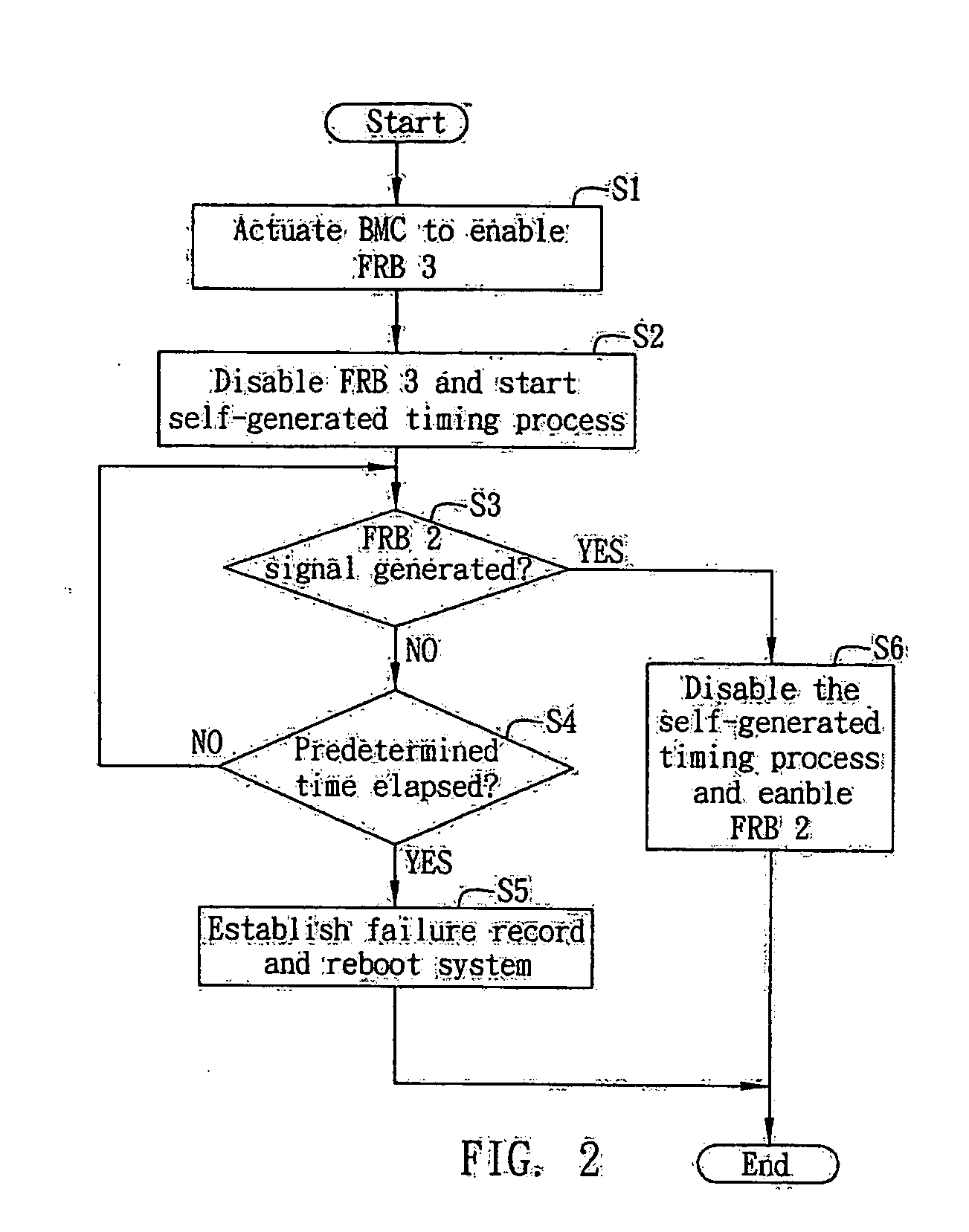
[0021] Referring to FIG. 1 and 2, FIG. 1 shows a basic structural block diagram required for a computer system that performs the method for detecting a switching failure of the present invention; FIG. 2 is an operational flowchart of the me...


PUM


Abstract

A method for detecting a switching failure, applied to a system having a Base Management Controller (BMC), a BIOS and a CPU under an Intelligent Platform Management Interface (IPMI), so as to avoid failure when the BMC switches from a Fault Resilient Booting (FRB) 3 mechanism to a FRB 2 mechanism. The method at includes the steps of allowing the BMC to perform the FRB 3 mechanism when power-on of the system is detected; canceling the FRB 3 mechanism by the BMC after the BIOS code is obtained by the CPU and starting a timing process for counting a predetermined time; and if the BIOS sends a command to the BMC within the predetermined time to enable the FRB 2 mechanism for monitoring a Power On Self Test (POST) performed by the BIOS, the BMC disabling the self-generated timing process, otherwise establishing and storing a failure record.

Description

FIELD OF THE INVENTION [0001] The present invention relates to a method for detecting a switching failure, and more particularly, to a method for detecting failure during switching from a Fault Resilient Booting (FRB) 3 mechanism to a FRB 2 mechanism defined under an Intelligent Platform Management Interface (IPMI) architecture. BACKGROUND OF THE INVENTION [0002] Along the rapid development of computer technology, processing power of computers increases tremendously. Development in network technology has also facilitated communication between computers, such that a computer at a terminal can successfully and quickly access information in a computer at another remote terminal, achieving information exchange between various different locations. [0003] For example, blade servers emerge as a result of combining computer and network technologies. The employment of blade servers enhances efficiency of network management. In order to utilize blade servers to their full extent, manufacturer...

Claims


Application Information

Patent Timeline
Patent Type & Authority Applications(United States)
IPC IPC(8): G06F11/00
CPCG06F11/0751
Inventor SHIH, WHPAN, CHIN-FONG
Owner INVENTEC CORP
Why Eureka
Try Eureka