Key switch structure

a key switch and structure technology, applied in contact mechanisms, emergency actuators, electrical devices, etc., can solve the problems of difficult to dispose of the el element directly below, the structure of the key switch cannot be used in an information processing device, a measurement instrument, or a medical instrument,

Inactive Publication Date: 2007-10-11
JIANGSU TRANSIMAGE TECH CO LTD
View PDF7 Cites 40 Cited by
  • Summary
  • Abstract
  • Description
  • Claims
  • Application Information

AI Technical Summary

Benefits of technology

[0010]A first aspect of the present invention provides a key switch structure comprising: a key top on which an unpainted character portion that is permeable to light is formed; a membrane sheet that comprises a contact portion and is permeable to light; a plate member that is disposed below the membrane sheet and is permeable to light; and a light source disposed below the plate member, wherein the unpainted character portion of the key top is lighted via the plate member and the membrane sheet by causing the light source to emit light.

Problems solved by technology

However, in the above-described conventional keyboard device of the key switch structure using an EL element, it is common for the lighting lifespan of the EL element to be about 3,000 hours, which is relatively short, and there has been the problem that the key switch structure cannot be employed in an information processing device, a measurement instrument, or a medical instrument whose use for several years is to be assured.
Moreover, there has also been the problem that the product becomes expensive because an inverter that supplies high-frequency / high-voltage alternating current in order to cause the EL element to emit light is necessary.
Further, when an EL element is disposed in a keyboard including a link mechanism portion widely employed in personal computers, it is difficult to dispose the EL element directly below the link mechanism portion disposed on the underside of the keyboard, and there is no choice but to dispose the EL element in a place other than directly below the link mechanism portion.
For that reason, there has also been the problem that it is difficult to obtain lighting of the keyboard that is uniform and good.

Method used


Image

  • Key switch structure
  • Key switch structure
  • Key switch structure

Examples


Embodiment Construction

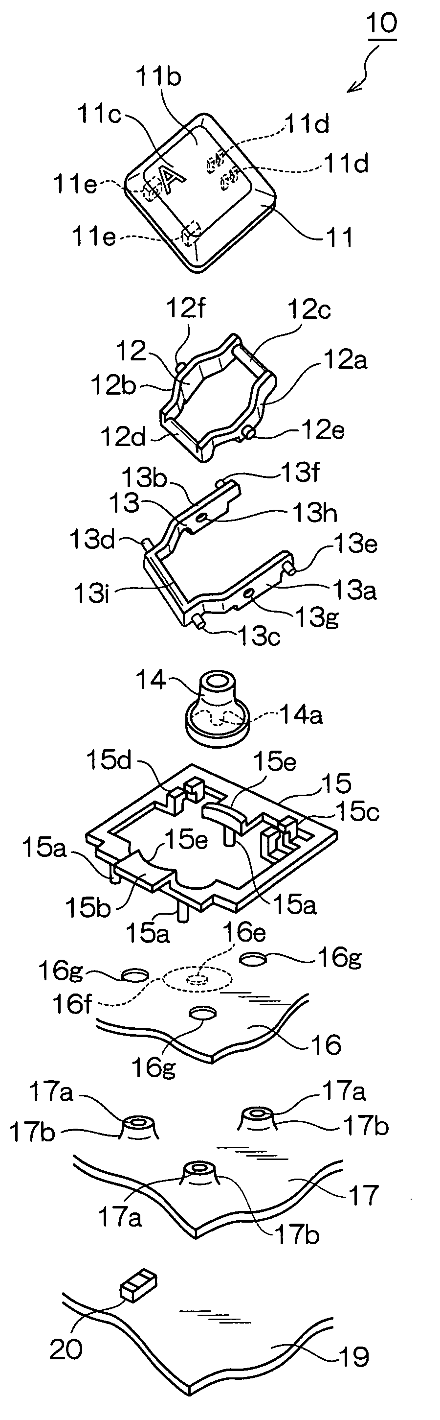
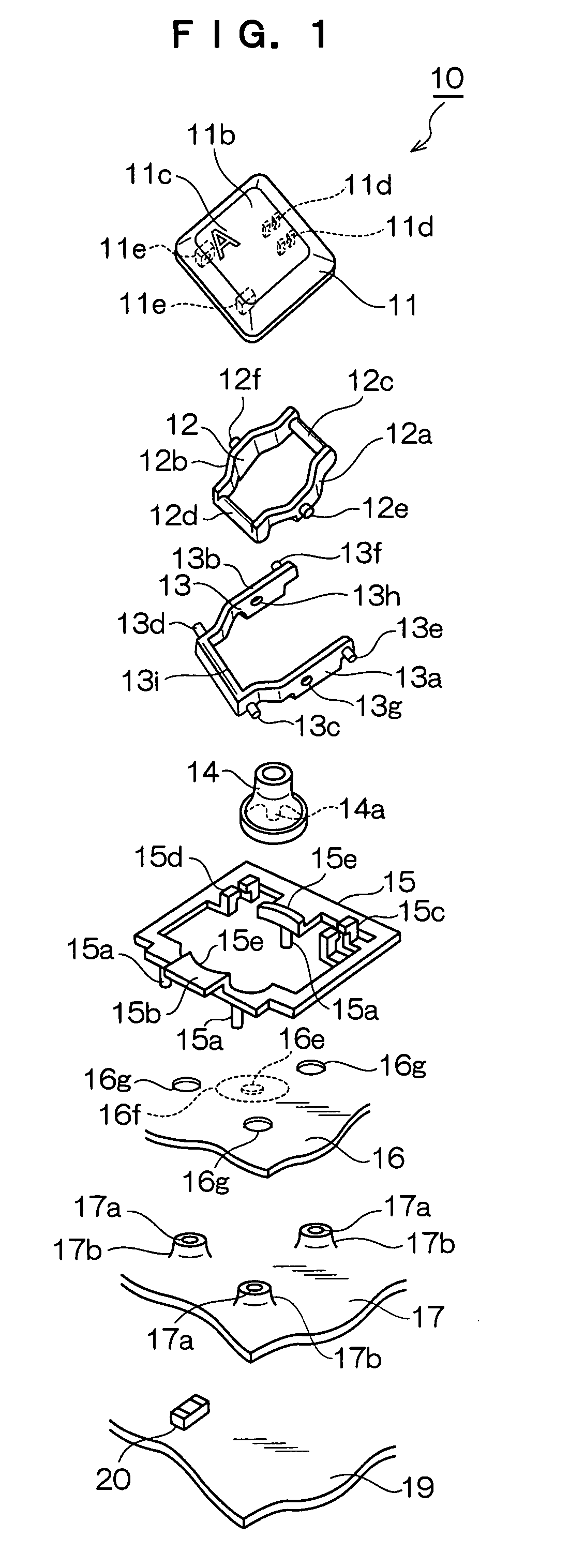
[0029]Exemplary embodiments of the present invention will be described below in accordance with the drawings. The same reference numerals will be given to elements in common throughout the drawings. FIG. 1 is an exploded perspective diagram showing a key switch structure of a first exemplary embodiment, and FIG. 2 is a cross-sectional diagram showing the key switch structure of the first exemplary embodiment.

[0030]In FIG. 1 and FIG. 2, a key switch 10 of the first exemplary embodiment is configured by: a key top 11; a first link member 12 disposed so as to be slidable with respect to the key top 11; a second link member 13 disposed so as to be rotatable with respect to the key top 11; a rubber dome (elastic member) 14 that bends when the key top 11 is depressed and causes the key top 11 to return to its original position when the depressing force is released; a holder 15 that holds the first and second link members 12 and 13; a membrane sheet 16 that includes a contact portion direc...


PUM


Abstract

A key switch structure includes a key top, a membrane sheet, a plate member, and a light source. The key top on which an unpainted character portion that is permeable to light is formed. The membrane sheet comprises a contact portion and is permeable to light. The plate member is disposed below the membrane sheet and is permeable to light. The light source is disposed below the plate member. The unpainted character portion of the key top is lighted via the plate member and the membrane sheet by causing the light source to emit light.

Description

CROSS-REFERENCE TO RELATED APPLICATION[0001]This application claims priority under 35 USC 119 from Japanese Patent Application No. 2006-106655, the disclosure of which is incorporated by reference herein.BACKGROUND OF THE INVENTION[0002]1. Field of the Invention[0003]The present invention relates to a key switch structure of a keyboard that is used as an input device in an information processing device, a measurement instrument, or a medical instrument, and in particular relates to a key switch structure including a lighting function that can ensure good operability even in a dark environment.[0004]2. Description of the Related Art[0005]Conventionally, the development of keyboard devices that can ensure good operability even in a dark environment has been carried out. For example, there is a keyboard device of the structure shown in FIG. 17. To describe this keyboard device using FIG. 17, a character or symbol is printed on the upper surface of a key top 1, an elastic member 2 and a...

Claims


Application Information

Patent Timeline
Patent Type & Authority Applications(United States)
IPC IPC(8): H01H9/00
CPCH01H3/125H01H13/83H01H2209/038H01H2209/06H01H2209/082H01H2215/006H01H2221/07H01H2219/03H01H2219/044H01H2219/056H01H2219/06H01H2219/062H01H2219/014
Inventor CHIBA, TOSHIMITOZUKA, ZENZOYAMADA, SHIGERU
Owner JIANGSU TRANSIMAGE TECH CO LTD
Why Eureka
Try Eureka