
Laser pulmonary vein isolation

a pulmonary vein and laser technology, applied in the field of laser pulmonary vein isolation, can solve the problems of difficult control of tissue local heating, undesirable effects of excessive local heating, and the effect of less effective medical procedures

Inactive Publication Date: 2006-02-14
BIOSENSE
View PDF28 Cites 561 Cited by
  • Summary
  • Abstract
  • Description
  • Claims
  • Application Information

AI Technical Summary

Benefits of technology

[0023]It is therefore a primary object of some aspects of the present invention to provide improved apparatus and method for electrically isolating the pulmonary vein by accomplishing a circumferential conduction block surrounding the pulmonary vein ostium in a single ablation application of laser light energy.
[0024]It is another object of some aspects of the present invention to reduce the time required to perform isolation of the pulmonary veins using a laser.
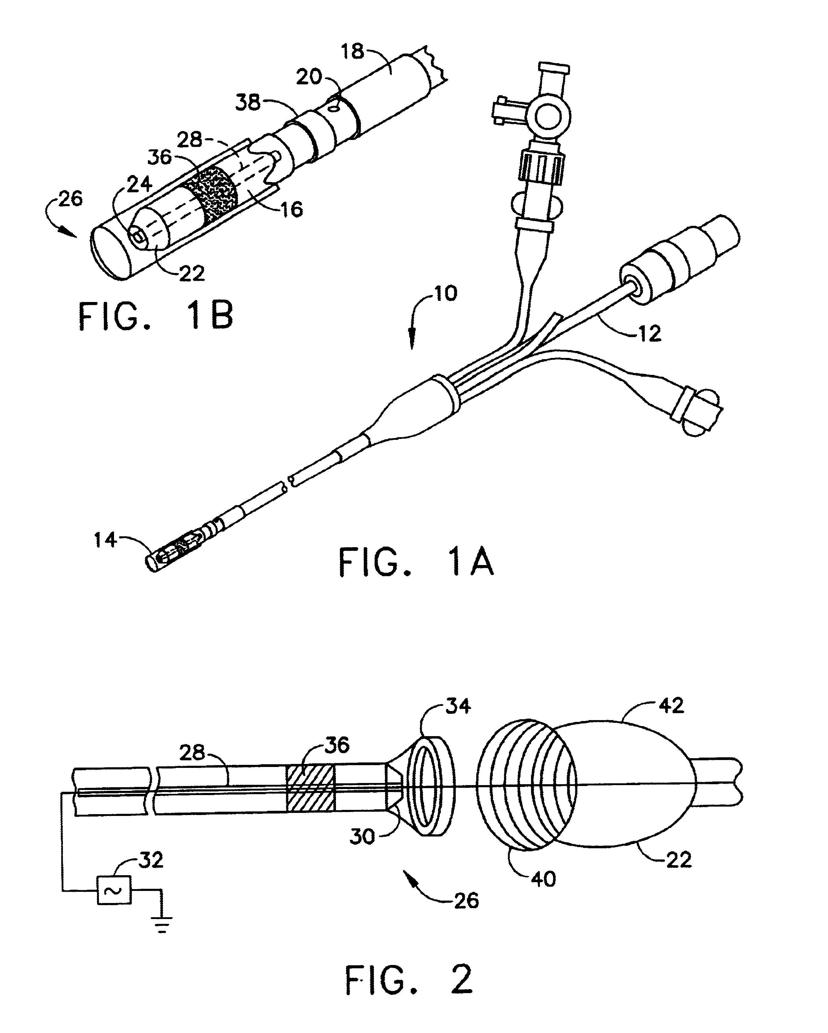
[0025]A catheter introduction apparatus provides an optical assembly for emission of laser light energy. In one application, the catheter and the optical assembly are introduced percutaneously, and transseptally advanced to the ostium of a pulmonary vein. An anchor such as an anchoring balloon is expanded to center a mirror in front of the ostium of the pulmonary vein, such that light energy is reflected from the mirror circumferentially onto the wall of the pulmonary vein when a laser light source is energized. A circumferential ablation lesion is produced around the ostium of the pulmonary vein, which effectively blocks electrical propagation between the pulmonary vein and the left atrium.

Problems solved by technology

A known drawback in the use of ultrasound energy for cardiac tissue ablation is the difficulty in controlling the local heating of tissue.
There are tradeoffs between the clinical desire to create a sufficiently large lesion to effectively ablate an abnormal tissue focus, or block an aberrant conduction pattern, and the undesirable effects of excessive local heating.
If the ultrasound device creates too small a lesion, then the medical procedure could be less effective, or could require too much time.
On the other hand, if tissues are heated excessively then there could be local charring effects due to overheating.
Such overheated areas can develop high impedance, and may form a functional barrier to the passage of heat.
The use of slower heating provides better control of the ablation, but unduly prolongs the procedure.

Method used


Image

  • Laser pulmonary vein isolation
  • Laser pulmonary vein isolation
  • Laser pulmonary vein isolation

Examples


Embodiment Construction

[0062]In the following description, numerous specific details are set forth in order to provide a thorough understanding of the present invention. It will be apparent to one skilled in the art, however, that the present invention may be practiced without these specific details. In other instances, well known circuits, control logic, and other apparatus have not been shown in detail in order not to unnecessarily obscure the present invention.

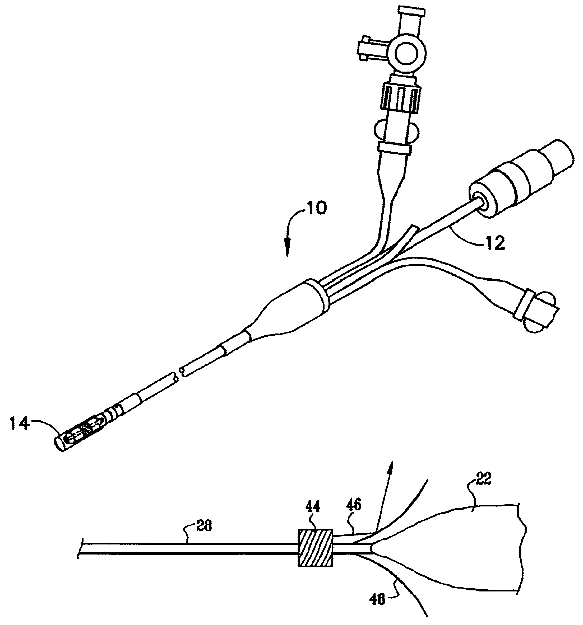
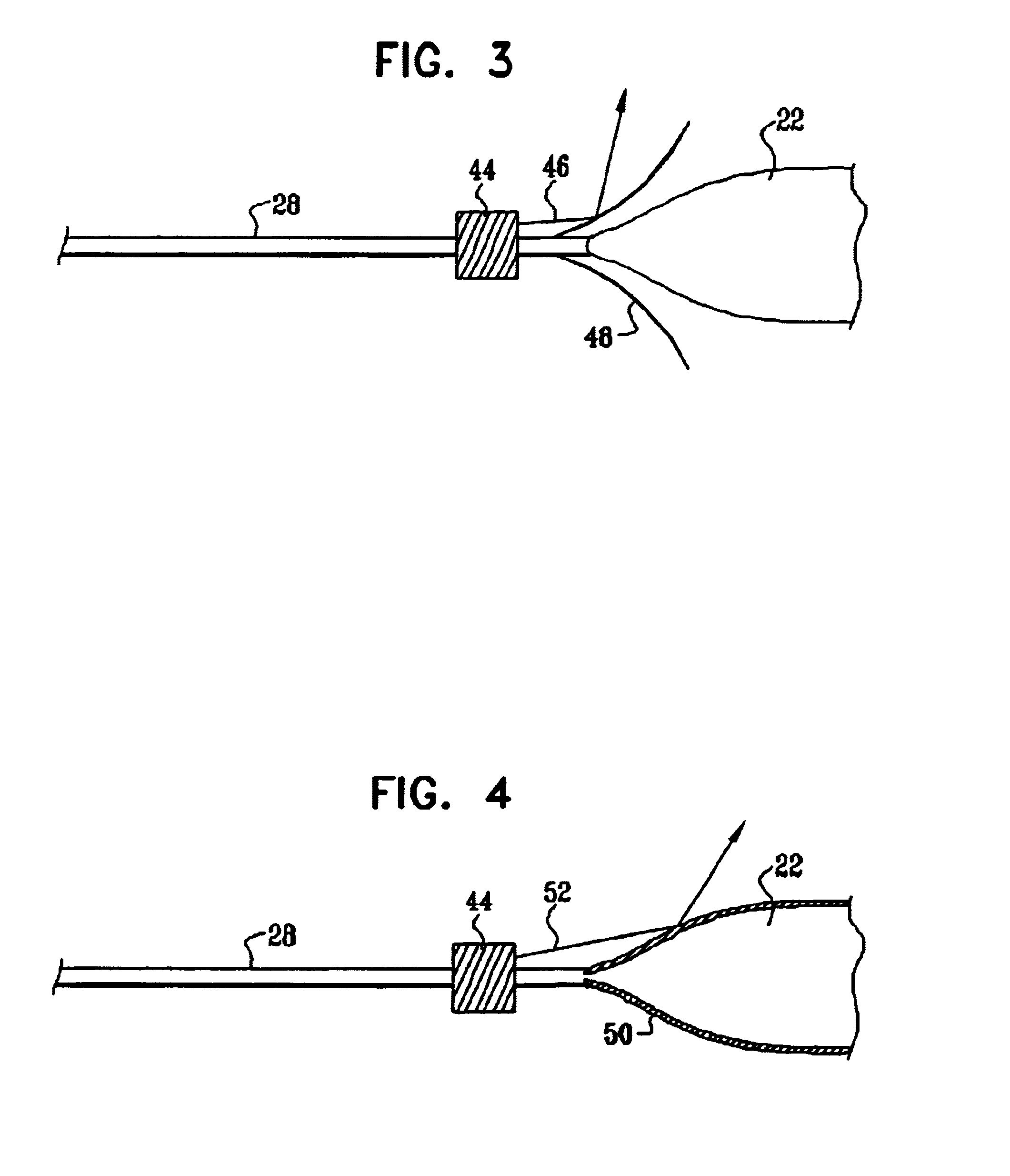
[0063]Turning now to the drawings, reference is made to FIG. 1A and 1B, which illustrate a medical device that is constructed and operative in accordance with a preferred embodiment of the invention. An intravascular catheter 10 has a proximal end 12 and a distal end 14. The distal end 14 is provided with at least one seal 16, and optionally a second seal 18. The seals 16, 18 are preferably inflatable balloons, made from rubber, polyurethane, or a similar elastic material. The catheter 10 has one or more lumens, which conduct fluid for inflating ...


PUM


Abstract

A catheter introduction apparatus provides an optical assembly for emission of laser light energy. In one application, the catheter and the optical assembly are introduced percutaneously, and transseptally advanced to the ostium of a pulmonary vein. An anchoring balloon is expanded to position a mirror near the ostium of the pulmonary vein, such that light energy is reflected and directed circumferentially around the ostium of the pulmonary vein when a laser light source is energized. A circumferential ablation lesion is thereby produced, which effectively blocks electrical propagation between the pulmonary vein and the left atrium.

Description

BACKGROUND OF THE INVENTION[0001]1. Field of the Invention[0002]This invention relates to methods and apparatus for the medical treatment of disease of the heart. More particularly, this invention relates to a method and apparatus for treating cardiac arrhythmias by ablating in a vicinity of pulmonary venous tissue.[0003]2. Description of the Related Art[0004]Tissue ablation from the inner walls of hollow viscera of the body generally, and the vascular system in particular, has been found to be useful in the treatment of various medical conditions. Technological developments in intravascular catheters, manipulative instruments adapted to intravascular catheters, and catheter localization techniques have especially benefited the field of cardiology. Percutaneous transcatheter ablation has been used successfully in the treatment of conduction defects and arrhythmias of various types. Today, atrial tachyarrhythmias are a common application for ablative therapy.[0005]Various ablative mo...

Claims


Application Information

Patent Timeline
IPC IPC(8): A61B18/18A61B18/20A61B17/22A61B18/22A61B18/24
CPCA61B18/24A61B2018/2272A61B2017/22051
Inventor SCHWARTZ, YITZHACKGOVARI, ASSAFBEN-HAIM, SHLOMOYARON, URILEATHAM, MARCIA
Owner BIOSENSE
Learn More