Imaging module having lead frame supported light source or sources

a technology of lead frame and light source, applied in the field of imaging modules, can solve the problems of optimal placement of light source with respect to optics, and achieve the effect of facilitating the removal of light source generated heat and additional rigidity

Active Publication Date: 2014-12-23
HAND HELD PRODS
View PDF8 Cites 638 Cited by
  • Summary
  • Abstract
  • Description
  • Claims
  • Application Information

AI Technical Summary

Benefits of technology

[0006]It has been discovered that the desired optimal light source placement can be effected by providing a light source support that is precisely located in a predetermined position, by being fixed, in that position, within a housing. Also, provided as a thermally conductive element, the light source support facilitates the removal of light source generated heat, while the housed support provides additional rigidity to the module.

Problems solved by technology

With respect to imaging modules and the light sources they employ, there have been difficulties associated with optimal placement of the light sources with respect to their optics.
Problems in this regard have been ascertained as to illumination and aiming light sources and optics.

Method used


Image

  • Imaging module having lead frame supported light source or sources
  • Imaging module having lead frame supported light source or sources
  • Imaging module having lead frame supported light source or sources

Examples


Embodiment Construction

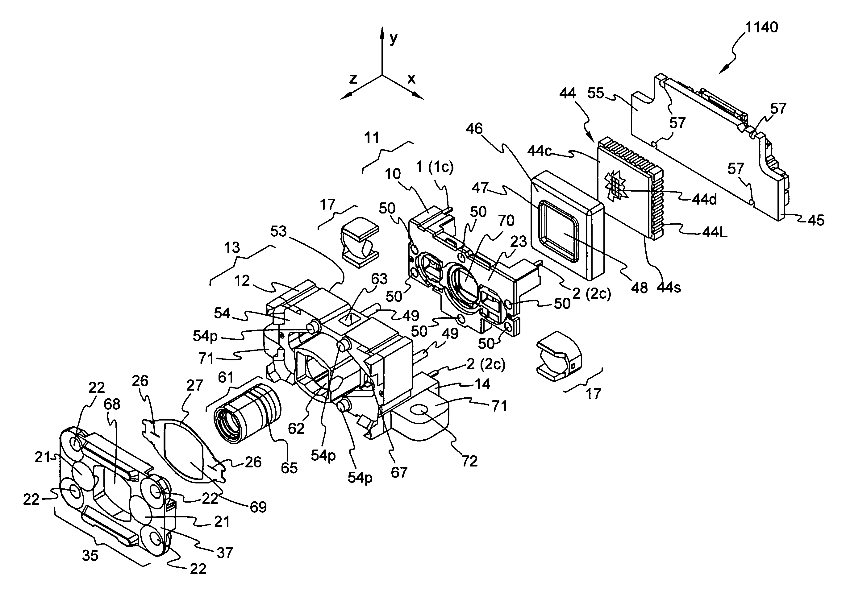
[0057]An imaging module of the invention—FIG. 8 showing an embodiment thereof, in the assembly state, as module 1140—includes a light source support bearing at least one illumination light source, and / or a light source support bearing at least one aiming light source. The former light source support is also identified as an illumination light source support, and the latter light source support correspondingly is also identified as an aiming light source support.

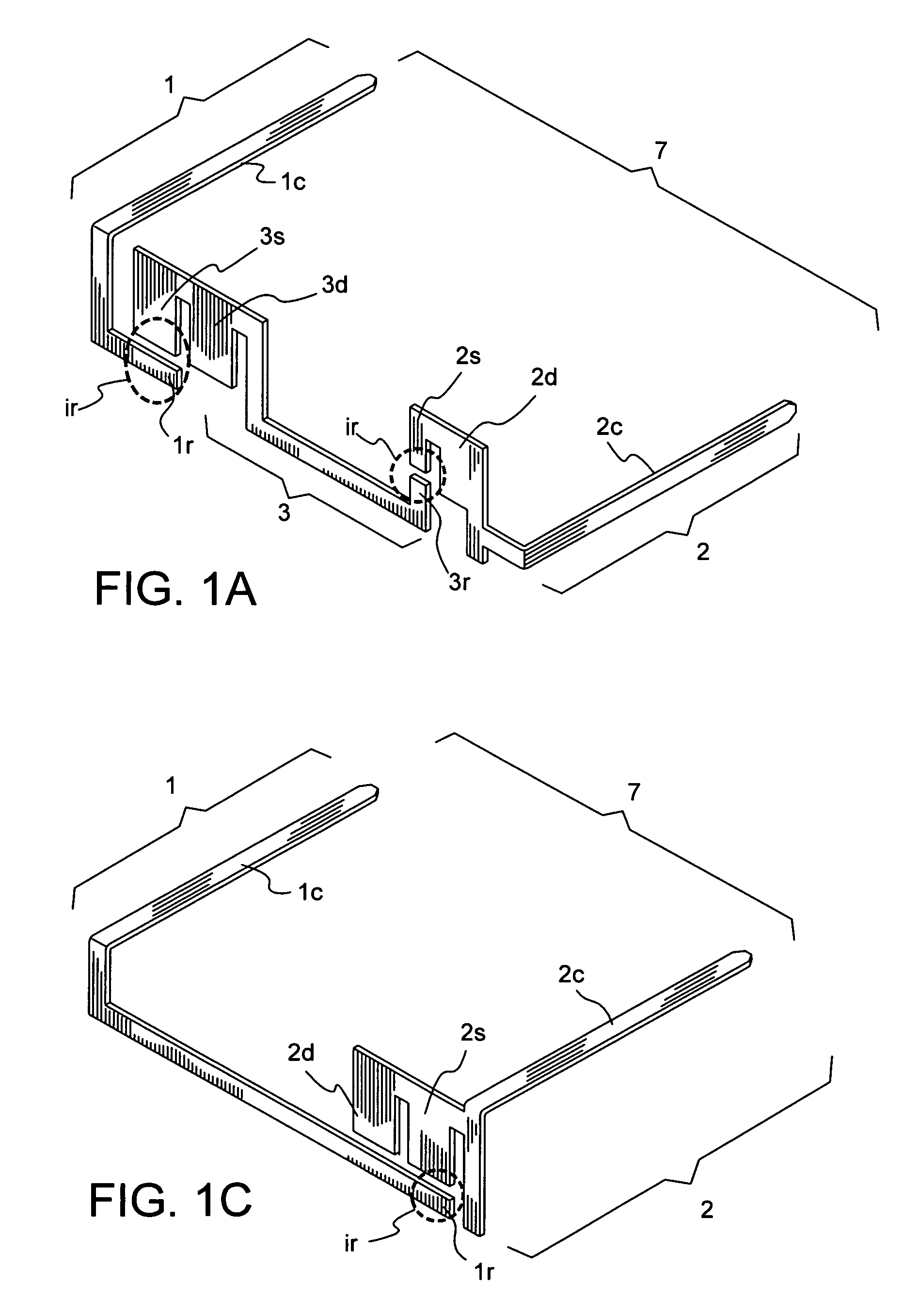
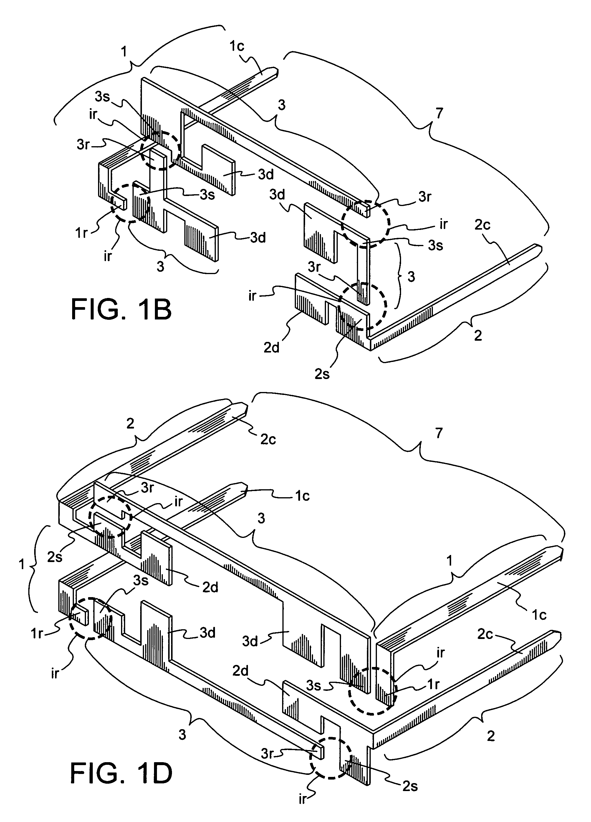
[0058]Preferred light source supports of the invention are lead frames. Accordingly, preferred illumination light source supports are illumination light source lead frames, or illumination lead frames, and preferred aiming light source supports are aiming light source lead frames, or aiming lead frames.

[0059]The illumination and aiming light sources of the invention serve the functions conventional in the art for these components.

[0060]In this regard, the purpose of illumination light sources—where they are employed—is to ens...


PUM


Abstract

An imaging module for data collection devices, such as bar code scanners. The module includes an aiming or illumination light source or sources, seated on a support is mounted in a housing. The support is fixed in the housing to provide for its precise placement therein, in a predetermined position.

Description

CROSS-REFERENCE TO RELATED APPLICATIONS[0001]This application claims benefit under 35 USC §119(e) of prior U.S. Provisional Patent Application No. 60 / 906,726, filed Mar. 13, 2007. This provisional patent application is incorporated herein in its entirety, by reference thereto.BACKGROUND OF THE INVENTION[0002]1. Field of the Invention[0003]The present invention pertains to imaging modules, particularly imaging modules for imaging and data collection devices.[0004]2. Description of Background and Other Information[0005]With respect to imaging modules and the light sources they employ, there have been difficulties associated with optimal placement of the light sources with respect to their optics. Problems in this regard have been ascertained as to illumination and aiming light sources and optics.SUMMARY OF THE INVENTION[0006]It has been discovered that the desired optimal light source placement can be effected by providing a light source support that is precisely located in a predeter...

Claims


Application Information

Patent Timeline
Patent Type & Authority Patents(United States)
IPC IPC(8): G06K7/10
CPCG06K7/10712
Inventor HAVENS, WILLIAM H.PITOU, DAVID STEWARTMCCOLLOCH, LAURENCE RAYBARBER, CHARLES PAULGANNON, COLLEEN PATRICIA
Owner HAND HELD PRODS
Why Eureka
Try Eureka