Liquid-filled balloons for immersion lithography

a liquid-filled balloon and lithography technology, applied in the field of immersion lithography, can solve the problems of limiting the ability to continue scaling down, altering the unmasked photoresist, and fast approaching optical lithography

Active Publication Date: 2005-07-21
TWITTER INC
View PDF5 Cites 552 Cited by
  • Summary
  • Abstract
  • Description
  • Claims
  • Application Information

AI Technical Summary

Benefits of technology

[0015] In a first aspect of the invention, a photolithographic sub-system adapted for a photolithographic system for projecting light onto a resist covering at least a portion of a substrate is provided. The photolithographic sub-system includes a container havi

Problems solved by technology

However, optical lithography is rapidly approaching physical barriers that limit the ability to continue scaling down.
As the projected light hits the photoresist on the silicon wafer, it may alter the unmasked photoresist.
A number of practical issues to implementing immersion lithography exist.
Maintaining a consistent bubble-free liquid between the lens and the wafer is very difficult unde

Method used


Image

  • Liquid-filled balloons for immersion lithography
  • Liquid-filled balloons for immersion lithography
  • Liquid-filled balloons for immersion lithography

Examples


Embodiment Construction

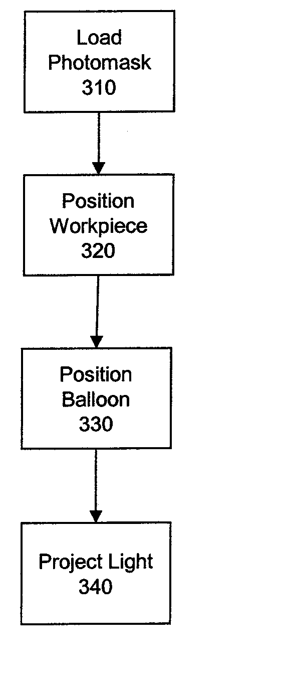
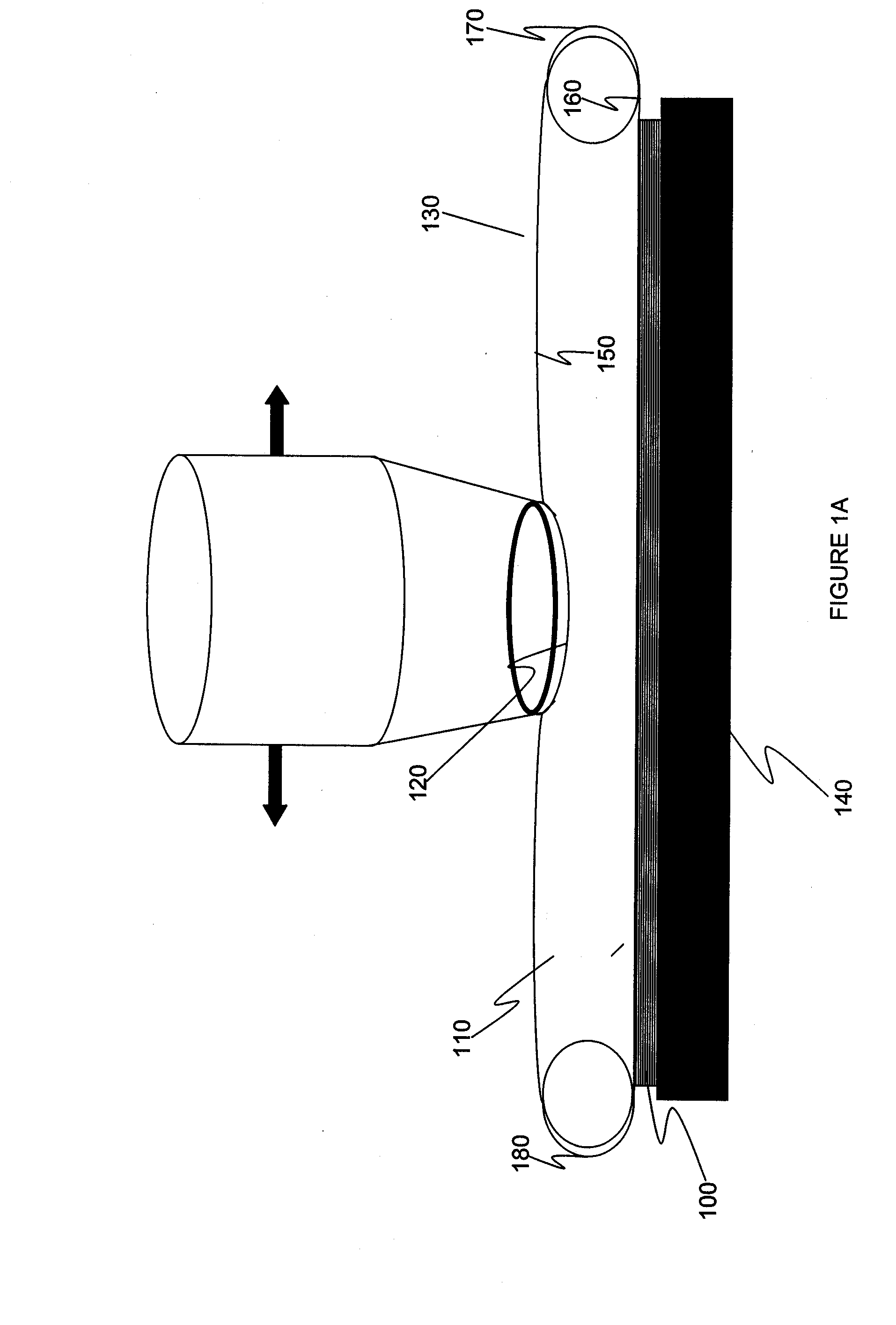
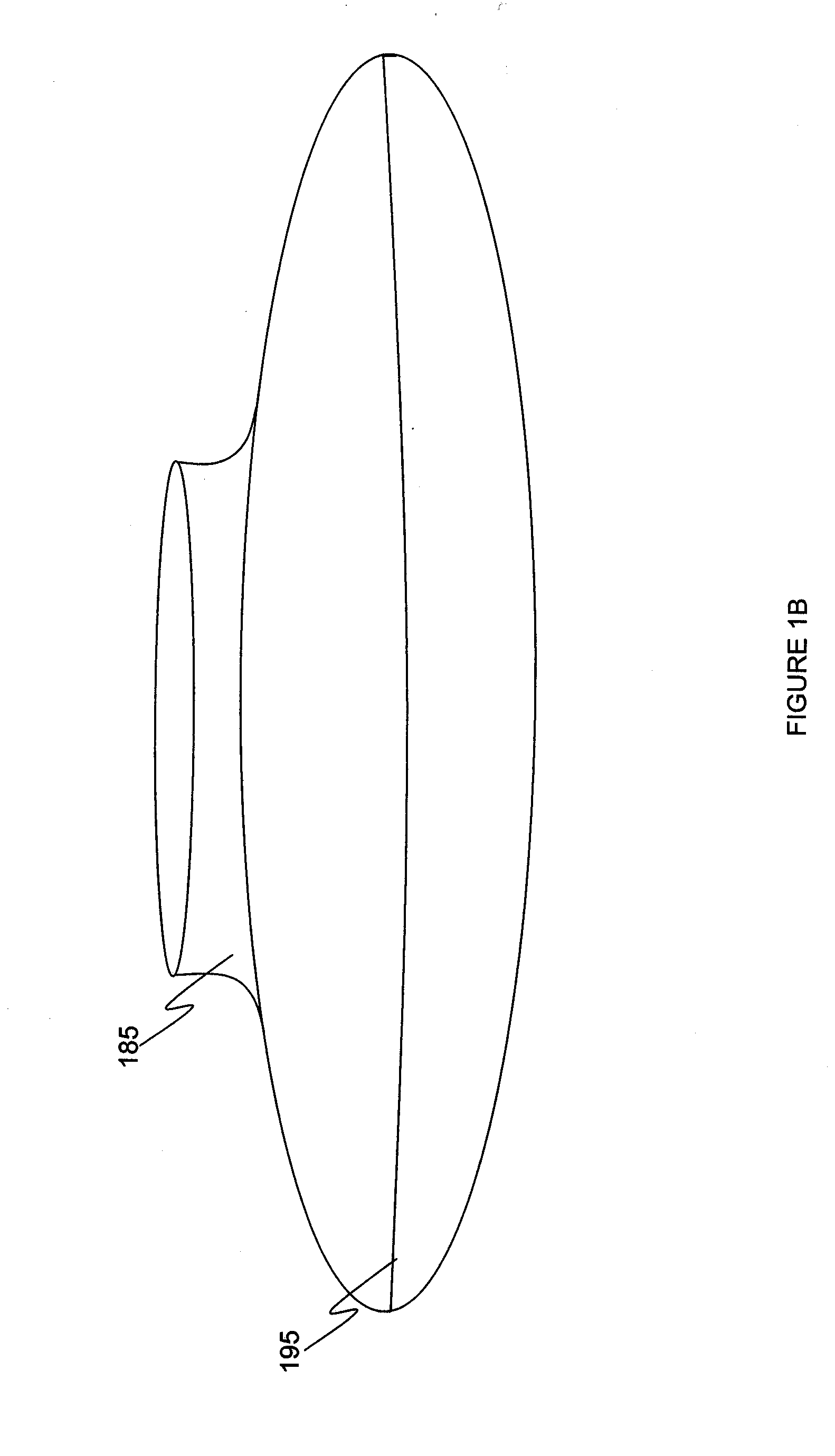
[0022] An exemplary embodiment of the invention provides a liquid filled balloon that may be positioned between a workpiece, such as a semiconductor structure covered with a photoresist, and a lithography light source. The term “balloon” as used herein means a container for a fluid, whether or not the container is inflatable or otherwise expandable. The exemplary balloon includes a thin pliable membrane that exhibits good optical and physical properties. Liquid contained in the balloon also exhibits good optical properties, including a refractive index higher than that of air. Light from the lithography light source passes through a mask, through lens assembly, through a top layer of the balloon membrane, through the contained liquid, through a bottom layer of the balloon membrane, and onto the workpiece where it alters portions of the photoresist. As the liquid has a low absorption and a higher refractive index than air, the liquid-balloon system enhances resolution. Thus, the ball...


PUM


Abstract

A liquid-filled balloon may be positioned between a workpiece, such as a semiconductor structure covered with a photoresist, and a lithography light source. The balloon includes a thin membrane that exhibits good optical and physical properties. Liquid contained in the balloon also exhibits good optical properties, including a refractive index higher than that of air. Light from the lithography light source passes through a mask, through a top layer of the balloon membrane, through the contained liquid, through a bottom layer of the balloon membrane, and onto the workpiece where it alters portions of the photoresist. As the liquid has a low absorption and a higher refractive index than air, the liquid-filled balloon system enhances resolution. Thus, the balloon provides optical benefits of liquid immersion without the complications of maintaining a liquid between (and in contact with) a lithographic light source mechanism and workpiece.

Description

BACKGROUND OF INVENTION [0001] 1. Field of the Invention [0002] The invention generally relates to immersion lithography for semiconductor fabrication and, more particularly, to a liquid-filled balloon for maintaining a liquid between a photolithographic lens and a wafer. [0003] 2. Background Description [0004] A driving force in the continual improvement in complexity and cost of integrated circuits is uninterrupted enhancement of photolithography, particularly the ability to pattern smaller and smaller features. However, optical lithography is rapidly approaching physical barriers that limit the ability to continue scaling down. [0005] Lithography uses radiation to transfer images onto a substrate coated with a material reactive to the radiation. Radiation in the form of light, for example, ultraviolet light, may be directed onto a mask (i.e., a photomask) defining a pattern. After shining through or reflecting from a mask the light is projected through a series of optical lenses ...

Claims


Application Information

Patent Timeline
IPC IPC(8): A61B18/18G03C5/10G03C5/20G03F7/20H01L21/00
CPCY10S438/947G03F7/70341
Inventor HAKEY, MARK C.HORAK, DAVID V.KOBURGER, CHARLES W. IIIMITCHELL, PETER H.
Owner TWITTER INC
Why Eureka
Try Eureka