Optical films containing optical retardation-enhancing additive

a technology of optical retardation and additive, which is applied in the field of stretched optical films, can solve the problems of poor contrast ratio, negative out-of-plane retardation, and unsatisfactory rth in the a-plate, and achieve the effects of improving the retardation compensation of optical devices, improving image quality of lcd displays, and large viewing angles

Inactive Publication Date: 2016-04-12
EASTMAN CHEM CO
View PDF48 Cites 0 Cited by
  • Summary
  • Abstract
  • Description
  • Claims
  • Application Information

AI Technical Summary

Benefits of technology

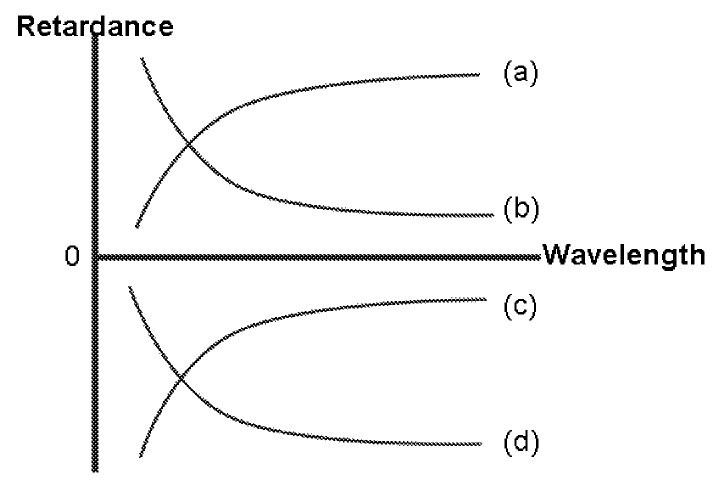
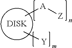
[0027]It has been surprisingly discovered that quarter wave plates comprising cellulose ester polymers and additives and having normal dispersion can be obtained in stretched films. It has also been unexpectedly discovered that this invention provides an additive that is capable of shifting the negative value of the out-of-plane retardation (Rth) of an unstretched optical film to more negative values, thereby improving the retardation compensation of an optical device such as a liquid crystal display (LCD). Thus, the invention has a utility for improving image quality of an LCD display, such as large viewing angle, high contrast ratio and less color shift. For example, the present invention provides for high negative C-plate (“−C plate”) behavior using cellulose esters combined with unique additives or retardation enhancers by conventional solvent casting process. Their optical properties are suitable for different types of liquid crystal displays, such as VA, TN, STN, etc.

Problems solved by technology

For example, in a vertically aligned (VA) mode liquid crystal display (LCD), the liquid crystal molecules in the LC cell are aligned in a homeotropic manner, which results in positive out-of-plane retardation.
In other types of devices, such as in-plane switch (IPS) mode LCD and 3D glasses, however, the Rth exhibited in the A-plate is not desirable since it can give rise to phase shift in off-axis light and lead to light leakage.
However optical birefringence requirements currently often dictate how compensation films will be used.
For example, for a typical set of crossed polarizers used in an LCD, there is significant light leakage along the diagonals (leading to poor contrast ratio), particularly as the viewing angle is increased.
These films must have certain well defined birefringences (or retardations) that vary depending on the type of liquid crystal cell used, since the liquid crystal cell itself will also impart an undesirable optical retardation that must be corrected.
Some of these compensation films are easier to make than others, so compromises are often made between performance and cost.
Certain styrenics and acrylics are known to have negative birefringent behavior due to their rather bulky side groups.

Method used


Image

  • Optical films containing optical retardation-enhancing additive
  • Optical films containing optical retardation-enhancing additive
  • Optical films containing optical retardation-enhancing additive

Examples


example 1

Preparation of Cellulose Ester Film 1 Having Normal Dispersion Curve

[0092]A solution of cellulose ester polymer was prepared by mixing a cellulose acetate propionate (45 g) having DS of acetate (DSAc)=0.18, DS of propionate (DSPr)=2.50, and DSOH=0.32 in a solvent blend, methylene chloride / ethanol (90 / 10 wt. %), 363 g, followed by the addition of the additive, 2-naphthyl benzoate, 4.45 g. The resulting mixture was placed on a roller for 24 hours to yield a uniform solution.

[0093]The solution prepared above was cast onto a glass plate using a doctor blade to obtain a film with the desired thickness. Casting was conducted in a fume hood by an automatic drawdown machine. The relative humidity of the hood was controlled at 40%-50%. After casting, the film was allowed to dry for 45 minutes under a cover pan to minimize the rate of solvent evaporation. After the pan was removed, the film was allowed to dry for 15 more minutes and subsequently peeled off from the glass. The free standing fi...

example 2

Preparation of Cellulose Ester Film 2 Having Normal Dispersion Curve

[0097]A solution of cellulose ester polymer was prepared by mixing a cellulose acetate (45 g) having DSAc=2.84, DSOH=0.16 in a solvent blend, methylene chloride / ethanol (92 / 8 wt. %), 357 g, followed by the addition of the additive, 2-naphthyl benzoate, 3.65 g. The resulting mixture was placed on a roller for 24 hours to yield a uniform solution.

[0098]The solution prepared above was cast onto a glass plate as described in Example 1 to obtain a film with the desired thickness. The resulting film (CE-2) was stretched according to Example 1 at various temperatures to a stretch ratio ranging from 1.25 to 1.40. The results are listed in Table 2.

[0099]

TABLE 2Retardations of the Stretched Cellulose Film 2Film ThicknessAfterStretch StretchingRatioRe(589),Rth(589),Re(450) / Re(650) / (microns)(TD × MD)nmnmRe(550)Re(550)CE-2a741 × 1.30 at 117.6−161.11.0140.999165° C.CE-2b781 × 1.25 at125.7−162.91.0130.999167.5° C.CE-2c801 × 1.40 a...

example 3

Preparation of Cellulose Ester Film 3 Having Normal Dispersion Curve

[0100]A solution of cellulose ester polymer was prepared by mixing a cellulose acetate propionate (48 g) having DSAc=1.59, DSPr=0.85, DSOH=0.56 in a solvent blend, methylene chloride / ethanol (90 / 10 wt. %), 352 g, followed by the addition of the additive, naphthalene, 4.8 g. The resulting mixture was placed on a roller for 24 hours to yield a uniform solution.

[0101]The solution prepared above was cast onto a glass plate as described in Example 1 to obtain a film with the desired thickness. The resulting film (CE-3) was stretched according to Example 1 at 160° C. to a stretch ratio ranging from 1.06 to 1.08. The results are listed in Table 3.

[0102]

TABLE 3Retardations of the Stretched Cellulose Film 3FilmThicknessAfterStretch StretchingRatioRe(589),Rth(589),Re(450) / Re(650) / (microns)(TD × MD)nmnmRe(550)Re(550)CE-3a821 × 1.08 at 136.0−214.71.0080.995160° C.CE-3b801 × 1.07 at 117.4−200.41.0070.996160° C.CE-3c821 × 1.06 at...


PUM

PropertyMeasurementUnit
thicknessaaaaaaaaaa
thicknessaaaaaaaaaa
thicknessaaaaaaaaaa

Abstract

The present invention pertains to an unstretched optical film comprising an additive for enhancing retardation in the thickness direction (Rth) and methods for making the optical film.

Description

CROSS REFERENCES TO RELATED APPLICATIONS[0001]This application is a continuation-in-part of U.S. application Ser. No. 14 / 108,810, filed Dec. 17, 2013.FIELD OF THE INVENTION[0002]This invention pertains to a stretched optical film for use as a quarter wave plate (QWP) having a normal wavelength dispersion curve. More specifically, this invention relates to a quarter wave plate based on cellulose ester polymer. This invention also relates to an unstretched optical film containing an additive for enhancing retardation in the thickness direction. More specifically, this invention provides an additive that is capable of increasing the negative value of the out-of-plane retardation (Rth) of an optical film.BACKGROUND OF THE INVENTION[0003]It is known in the art of optical compensation that the phase retardation of light varies according to wavelength, causing color shift and contrast ratio reduction. This wavelength dependence (or dispersion) characteristic of the compensation film may be...

Claims


Application Information

Patent Timeline
Patent Type & Authority Patents(United States)
IPC IPC(8): G02B1/08G02B5/30C08J5/18
CPCG02B5/3083C08J5/18C08J2301/12C08J2301/14
Inventor WANG, BINKUO, THAUMINGDONELSON, MICHAEL EUGENEMCWILLIAMS, DOUGLAS STEPHENS
Owner EASTMAN CHEM CO
Why Eureka
Try Eureka