Manufacturing method of polymer film

a polymer film and manufacturing method technology, applied in the field of manufacturing methods of polymer films, can solve the problems of difficult to produce film with high quality, low accuracy of film thickness, and generation of minute streaks (die lines) on the film, and achieve high retardation value, superior optical properties, and no degradation of transparency

Inactive Publication Date: 2010-03-30
FUJIFILM CORP
View PDF16 Cites 0 Cited by
  • Summary
  • Abstract
  • Description
  • Claims
  • Application Information

AI Technical Summary

Benefits of technology

[0010]An object of the present invention is to provide a manufacturing method which can stably produce a polymer film having high retardation value and superior transparency. The polymer film obtained by the present invention has optical properties suitable as a phase difference film for VA mode, IPS mode and OCB mode.
[0013]According to the present invention, the casting drum whose surface is cooled to the predetermined temperature range is used as the support on which the dope is cast, the casting dope becomes to have the self-supporting property by the cooling solidification, the wet film obtained by peeling the casting film from the support is dried to be the polymer film, and the polymer film is further dried and stretched in the width direction thereof while conveyed with both side edges thereof being held by the clips. The pin tenter with the plural pins is used for drying the wet film, and the clip tenter with clips is used for stretching the polymer film. Accordingly, a high retardation value can be applied to the polymer film without degrading transparency, and the polymer film can have superior optical properties.

Problems solved by technology

However, in this method, accuracy of the film thickness is low, and minute streaks (die lines) are generated on the film.
Accordingly, it is difficult to produce the film with high quality sufficient to be used as the optical film.
It is difficult for these methods to satisfy the increased requirement.
In addition, when the film is stretched by strong force to increase the retardation value, minute voids are possibly generated in film regions on which strong stresses are applied, that makes the film cloudy (degrading the transparency).
However, there is no statement in this publication about how to realize the required high retardation value for the film to be used in the LCD and the like.
Since the wet film right after the peeling of the casting film from the support is considerably soft, it is difficult to dry the wet film while convey it stably.

Method used


Image

  • Manufacturing method of polymer film
  • Manufacturing method of polymer film
  • Manufacturing method of polymer film

Examples


example 1

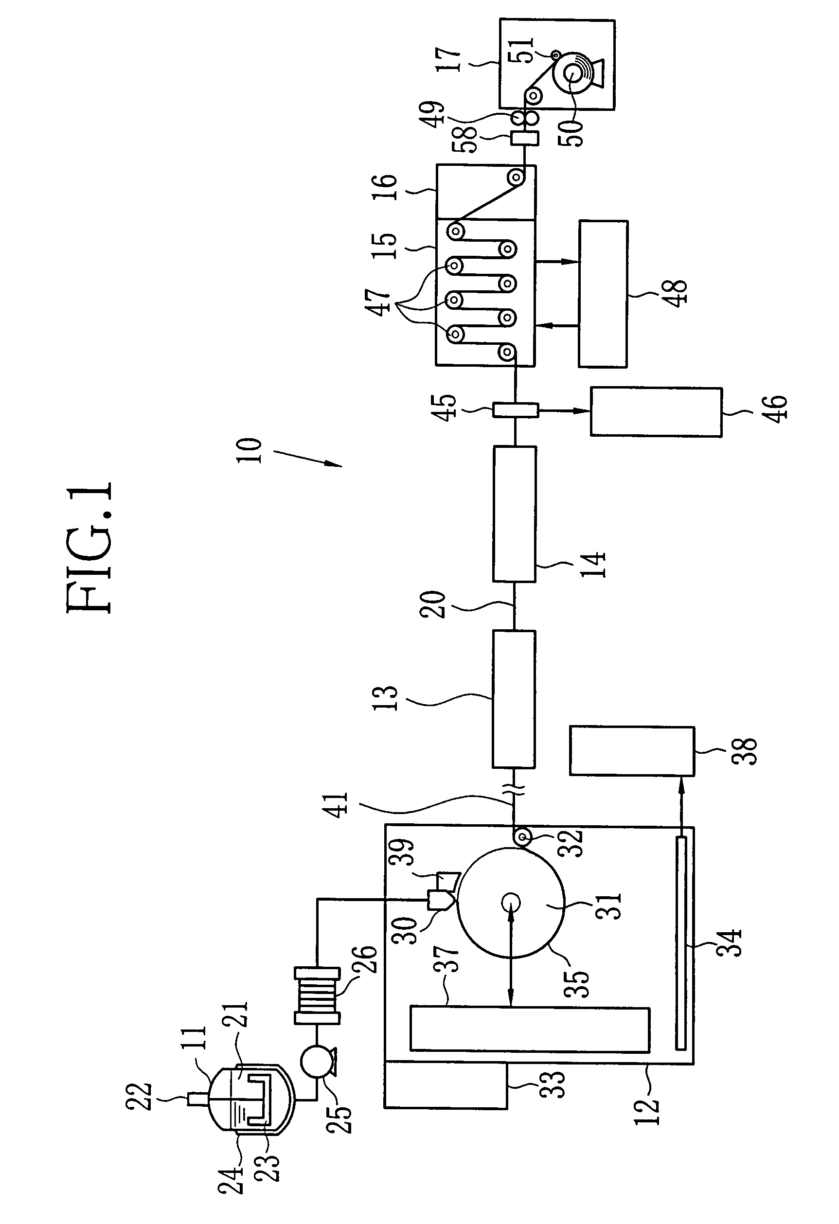
[0098]The dope 21 was prepared from following materials by the dope producing apparatus shown in FIG. 5. The composition of the dope 21 is shown below.

[0099]

Cellulose triacetate 100 mass. pct(substitution degree of acetyl group was 2.84, viscometricaverage degree of polymerization was 306, moisture content was0.2 mass. %, viscosity of 6% by mass of dichloromethane solutionwas 315 mPa · s, powder whose average of particle diameter was1.5 mm and standard deviation of the particle diameter was 0.5 mm)Dichloromethane (the first component of the solvent) 320 mass. pctMethanol (the second component of the solvent)  83 mass. pct1-Butanol (the third component of the solvent)  3 mass. pctPlasticizerA (Triphenylphosphate) 7.6 mass. pctPlasticizerB (Diphenylphosphate) 3.8 mass. pctUV-absorbing agent a: 0.7 mass. pct2-(2′-hydroxy-3′,5′-di-tert-butylphenyl)benzotriazolUV-absorbing agent b: 0.3 mass. pct2-(2′-hydroxy-3′,5′-di-tert-amylphenyl)-5-chlorobenzotriazoleCitric acid ester mixture:0.006 m...

example 2

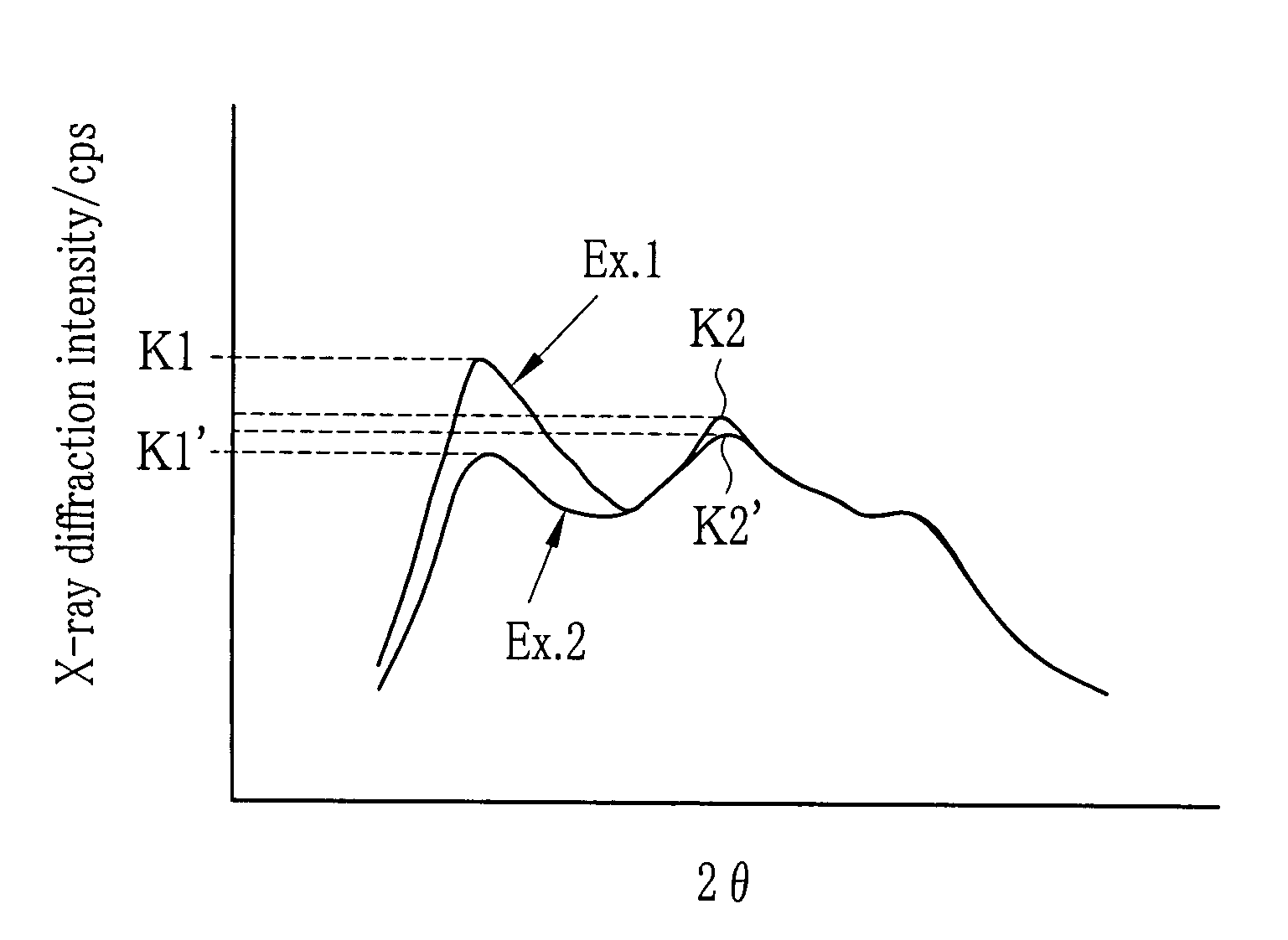
[0127]In Example 2, the apparatuses and conditions for manufacturing the film was same as Example 1, except that a casting belt was used as the support (that is, the casting film 35 becomes to have the self-supporting property not by cooling solidification, but by drying). When the X-ray diffraction intensity of the film 20 right before entering into the clip tenter 14 was measured by the reflection method, K1 was 12000 cps and K2 was 13200 cps (that is, K1

[0128]As a result of evaluation of the films 20 obtained by Example 1 and Example 2, it is found that the film 20 of Example 1 has the superior values both in the retardation and the transparency compared to the film 20 of Example 2. Especially, in regard to the transparency, the film of Example 1 has more than 6 times higher value than the film of Example 2. From the result, it is ...


PUM

PropertyMeasurementUnit
surface temperatureaaaaaaaaaa
temperatureaaaaaaaaaa

Abstract

A casting film is made by casting dope including polymer and solvent on a casting drum whose surface is cooled. The casting film becomes to have a self-supporting property by cooling solidification, and then peeled as a wet film from the casting drum. The wet film is fed into a pin tenter in which both side edges of the wet film is held by plural pins. The wet film is dried while conveyed through the pin tenter, to become a film. Next, the film having predetermined X-ray diffraction intensity is fed into a clip tenter. While the film whose both side edges are held by clips is conveyed, it is stretched in the width direction thereof at a stretch rate in a range of 15% to 40%, to control molecular orientation in the film.

Description

BACKGROUND OF THE INVENTION[0001]1. Field of the Invention[0002]The present invention relates to a manufacturing method of a polymer film usable as an optical functional film such as a protective film of a polarizing plate of a liquid crystal display, an optical compensation film or the like.[0003]2. Description of the Related Arts[0004]A polymer film (hereinafter called as the film) has superior optical transparency and flexibility, and allows reduction in thickness and weight thereof. Accordingly, the polymer film is used as various optical functional films. Especially, a cellulose ester film such as a cellulose acylate film is used as a photosensitive film, a protective film of a polarizing plate of a liquid crystal display (LCD) whose market is expanding recently, an optical compensation film and the like, because of having toughness and low birefringence.[0005]As methods for producing the film, there are a melt extrusion method and a solution casting method. The melt extrusion ...

Claims


Application Information

Patent Timeline
Patent Type & Authority Patents(United States)
IPC IPC(8): B29D7/00B29C55/00B29C71/00
CPCB29C41/26B29C55/08B29K2001/00B29K2995/0034
Inventor ARAI, TOSHINAOYAMAZAKI, HIDEKAZU
Owner FUJIFILM CORP
Why Eureka
Try Eureka