
Method and Device for Improving Spatial and Off-Axis Display Standard Conformance

a technology of standard conformance and display, applied in the field of fixed format displays, can solve problems such as inability to accept display behaviour, and achieve the effects of reducing significantly the contrast ratio, improving luminance uniformity, and significantly peak-luminan

Active Publication Date: 2007-10-11
FLUOR TECH CORP +1
View PDF8 Cites 181 Cited by
  • Summary
  • Abstract
  • Description
  • Claims
  • Application Information

AI Technical Summary

Benefits of technology

The present invention provides a method and device for correcting non-conformance in greyscale or colour values of a plurality of zones of pixel elements in a matrix display. The method involves storing characterization data that characterizes the non-conformance as a function of its drive signals and the viewing angle under which the pixel element is viewed. The pre-correcting function is then determined based on the characterization data and the viewing angle. The method can adapt the pre-correcting function based on changes in the viewing angle or environmental parameters, such as ambient light intensity or backlight intensity. The device includes a memory and a correction device for pre-correcting the driving signals to the pixel elements to achieve conformity with the enforced greyscale or colour display standard. The technical effects of the invention include improved spatial and off-axis conformance with the display standard, improved user experience, and reduced likelihood of non-conformance due to changing viewing angles or environmental parameters.

Problems solved by technology

Display behaviour may for example not be acceptable anymore if the viewing angle under which the zone of pixel elements is or is to be viewed at is outside a pre-determined range, e.g. becomes too large, or if an environmental or display dependent parameter changes, such as e.g. ambient light intensity or back-light intensity respectively.

Method used


Image

  • Method and Device for Improving Spatial and Off-Axis Display Standard Conformance
  • Method and Device for Improving Spatial and Off-Axis Display Standard Conformance
  • Method and Device for Improving Spatial and Off-Axis Display Standard Conformance

Examples


Embodiment Construction

[0068] The present invention will be described with respect to particular embodiments and with reference to certain drawings but the invention is not limited thereto but only by the claims. The drawings described are only schematic and are non-limiting. In the drawings, the size of some of the elements may be exaggerated and not drawn on scale for illustrative purposes.

[0069] It is to be noticed that the term “comprising”, used in the description and in the claims, should not be interpreted as being restricted to the means listed thereafter; it does not exclude other elements or steps. Thus, the scope of the expression “a device comprising means A and B” should not be limited to devices consisting only of components A and B. It means that with respect to the present invention, the only relevant components of the device are A and B.

[0070] Moreover, the terms top, bottom, over, under, left, right, height, width, horizontal and vertical, and the like in the description and the claims...


PUM


Abstract

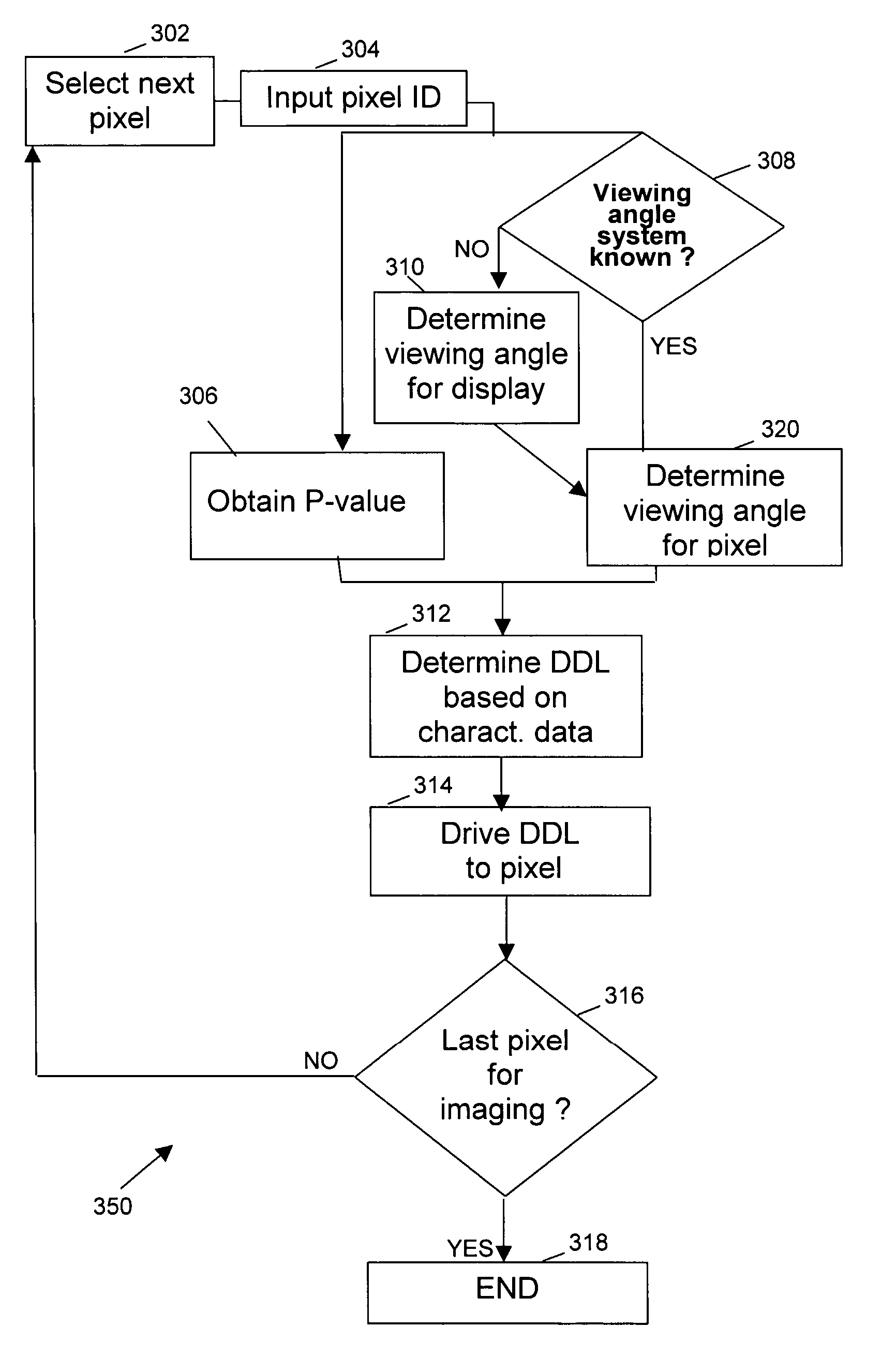
The invention describes a method for improving the spatial and off-axis conformance of display systems with respect to an enforced greyscale or colour display standard. In the display systems, the native transfer curve is obtained for each pixel or zone of pixels, i.e. as a function of position on the display and as a function of viewing-angle. Once that information is available, an optimal conversion scheme from P-value to DDL can be created for each position on the display and this for all possible viewing-angles. In use, the conversion scheme is used to obtain an improved DICOM behaviour. This optimisation is also done with respect to the viewing-angle, based on a pre-set, selectable or measured viewing angle.

Description

TECHNICAL FIELD OF THE INVENTION [0001] The present invention relates to systems and methods for electronic display devices, especially fixed format displays. More particularly, the invention relates to systems and methods for electronic display devices complying with enforced display standards, such as for example medical electronic display devices complying with enforced medical display standards like e.g. the DICOM standard. BACKGROUND OF THE INVENTION [0002] More and more medical displays are used as replacement for traditional film in radiology. Instead of using expensive film a radiologist looks at a digital image on a high-quality (typically greyscale) medical display. An additional advantage of the medical display is that the radiologist is able to perform image-processing operations on the medical image such as contrast enhancement, zoom . . . and this makes it easier to diagnose. It is obvious that medical displays require very high quality and quality control as they are ...

Claims


Application Information

Patent Timeline
Patent Type & Authority Applications(United States)
IPC IPC(8): G09G5/10G09G3/20
CPCG09G3/2092G09G2320/0233G09G2320/0276G09G2320/028G09G2360/144G09G2320/0606G09G2320/0626G09G2320/068G09G2320/0693G09G2320/0285G09G3/20G09G3/36G09G5/02
Inventor KIMPE, TOM
Owner FLUOR TECH CORP
Learn More