
Method and System for Generating Switching Timing Signal for Separating Transmitting and Receiving Signal in Optical Repeater of Mobile Telecommunication Network Using Tdd and Ofdm Modulation

a mobile telecommunication network and optical repeater technology, applied in electromagnetic repeaters, pulse techniques, synchronisation signal speed/phase control, etc., can solve the problems of limiting the availability of public services, high charge for use in existing mobile communication systems, and limiting the provision of very high-speed wireless internet services

Inactive Publication Date: 2007-10-11
SK TELECOM CO LTD
View PDF10 Cites 125 Cited by
  • Summary
  • Abstract
  • Description
  • Claims
  • Application Information

AI Technical Summary

Benefits of technology

The present invention provides a method and system for generating a switching timing signal in an optical repeater of a mobile communication network using a TDD scheme and an OFDM modulation scheme. The system includes a main donor, a remote, and a switching timing signal generating circuit. The method involves extracting a part of a RF signal from a coupler in the remote, correlating it with a reference signal generated in the switching timing signal generating circuit, detecting a frame start position, calculating the starting points of the downlink and uplink signals, and generating a switching timing signal based on the starting points. The system can separate the transmission signal into a downlink signal and an uplink signal by controlling the switch using the switching timing signal. The technical effect of the invention is to improve the efficiency and reliability of signal transmission in a mobile communication network.

Problems solved by technology

However, due to high cost for constructing a base station, the charge for using is high in an existing mobile communication system.
Further, due to a small screen size of a mobile communication terminal, there is a limit to provide very high speed wireless internet services for example a limit to use contents.
Furthermore, there is a limit to provide public services owing to the problem of radio wave interference and narrow using coverage in Wireless Local Area Network (hereinafter, referred to as WLAN).
However, the OFDM scheme has a characteristic to be sensitive to frequency offset of a carrier and phase noise, which becomes a main cause to affect the security of quadrature, that is, to deteriorate the capacity of a system, to have relatively a high ratio of average power to the maximum power comparative to one of a single carrier modulation, and to decrease power efficiency of an RF power amplifier.
It may cause undesirable results in cell-construction as well as in weakening the economical efficiency due to equipping expenses, installing expenses and maintenance and repair expenses, etc. to equip a plurality of new base stations for solving the shade of radio wave in the shade regions of radio wave.
However, it is impossible to distinguish an uplink signal from a downlink signal by using a duplex because it uses the same frequency in order to distinguish an uplink signal from a downlink signal when using the TDD scheme like the HPi system, etc.
However, because manufacturers of base stations and optical repeaters are generally various, in order to receive a switch controlling signal transmitted from a base station, it causes problems that an extra fee is needed for installing another modem in an optical repeater and the cause of obstacle is not founded easily for controlling a switch of an optical repeater.
Further, it is a defect that an extra procedure compensating the controlling signal by delay value of an optical cable is needed and an extra fee corresponding to this is needed.

Method used


Image

  • Method and System for Generating Switching Timing Signal for Separating Transmitting and Receiving Signal in Optical Repeater of Mobile Telecommunication Network Using Tdd and Ofdm Modulation
  • Method and System for Generating Switching Timing Signal for Separating Transmitting and Receiving Signal in Optical Repeater of Mobile Telecommunication Network Using Tdd and Ofdm Modulation
  • Method and System for Generating Switching Timing Signal for Separating Transmitting and Receiving Signal in Optical Repeater of Mobile Telecommunication Network Using Tdd and Ofdm Modulation

Examples


Embodiment Construction

[0039] Reference will now be made in detail to the preferred embodiments of the present invention. The same reference numerals are used to designate the same components as those shown in other drawings. In the following description of the present invention, a detailed description of known configurations and functions incorporated herein will be omitted when it may make the subject matter of the present invention rather unclear.

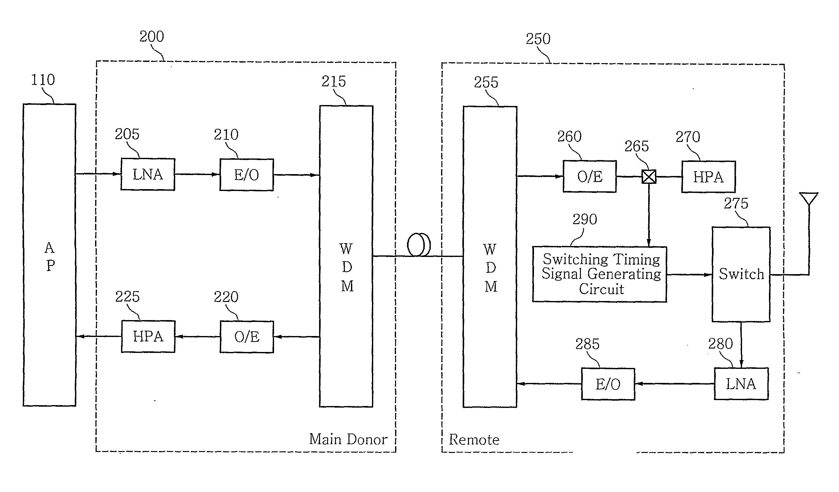
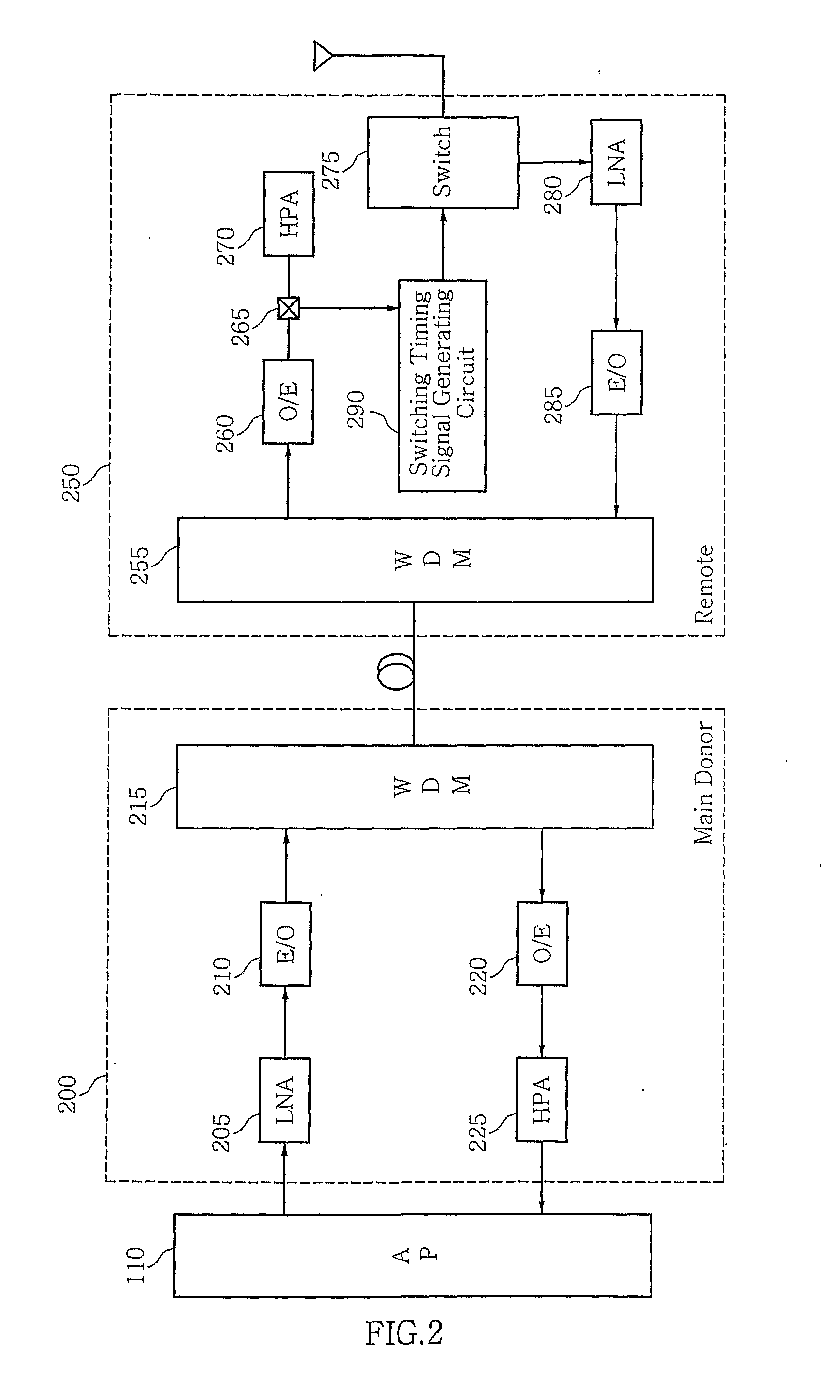
[0040]FIG. 2 is a diagram schematically showing the construction of an optical repeater according to a preferred embodiment of the present invention.

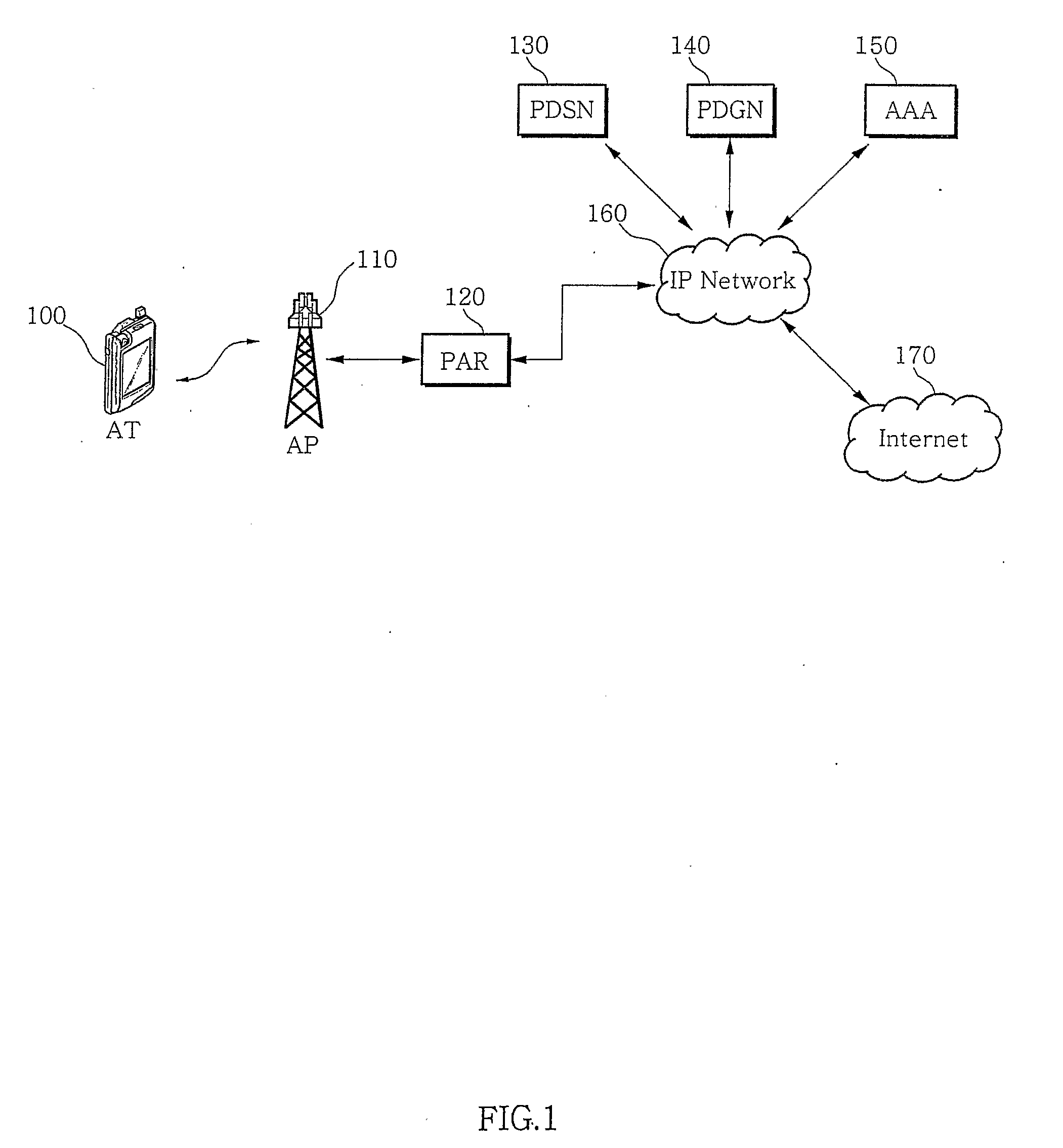
[0041] The optical repeater of the present invention makes both link communication possible by time-dividing the same frequency and distinguishing a downlink signal from an uplink signal due to using a TDD scheme, so that the Optical repeater is allowed to transmit a RF signal by using the same frequency between an AT 100 and an AP 110.

[0042] As shown in FIG. 2, the optical repeater according to a preferred emb...


PUM


Abstract

Disclosed are a method and system for generating switching a timing signal for separating a transmitting and receiving signal in an optical repeater of a mobile telecommunication network by using a Time Division Duplex (hereinafter, referred to as “TDD”) scheme and an Orthogonal Frequency Division Multiplexing (hereinafter, referred to as “OFDM”) modulation scheme, which transmits a part of a RF signal extracted from a coupler included in a remote of an optical repeater to a switching timing signal generating circuit, locates a frame start position of a RF signal by correlating a reference signal generated in a switching timing signal generating circuit with a RF signal extracted from a coupler, and is capable of transmitting a RF signal by distinguishing between a downlink signal and a uplink signal by using a switching timing signal in a switch when calculating a starting point of a downlink signal and a uplink signal included in an RF signal on the basis of a frame starting location, generating a switching timing signal by using it, and transmitting to a remote's switch.

Description

TECHNICAL FIELD [0001] The present invention relates to a method and system for generating a switching timing signal for separating a transmitting and receiving signal in an optical repeater of a mobile telecommunication network by using a Time Division Duplex (hereinafter, referred to as “TDD”) scheme and an Orthogonal Frequency Division Multiplexing (hereinafter, referred to as “OFDM”) modulation scheme. More particularly, the present invention relates to a method and system for generating switching a timing signal for separating a transmitting and receiving signal in an optical repeater of a mobile telecommunication network by using a TDD scheme and an OFDM modulation scheme, which transmits a part of a RF signal extracted from a coupler of a remote to a switching timing signal generating circuit when a RF signal transmitted from an Access Point (hereinafter, referred to as “AP”) is transmitted to a remote via a main donor of an optical repeater, locates a frame start position of...

Claims


Application Information

Patent Timeline
Patent Type & Authority Applications(United States)
IPC IPC(8): H04L27/26H04B10/11H04B10/29H04J11/00H04L7/00H04L7/08
CPCH04J3/0602H04J3/0685H04L27/2601H04L27/26H04J14/02
Inventor CHO, WOUNGSIKCHUN, YOUNGHOON
Owner SK TELECOM CO LTD
Learn More