Backlight image determining apparatus, backlight image determining method, backlight image correction apparatus, and backlight image correction method

a technology of backlight image and determining method, which is applied in the field of backlight image determining apparatus, backlight image determining method, backlight image correction apparatus, backlight image correction method, etc., can solve the problem of inability to suitably judge whether the image to be determined is a backlight image, the original image quality and the like of the image to be determined is compromised, and the risk of a backlight enhancement process being performed on an image that is not a backlight image is no

Inactive Publication Date: 2007-10-11
SEIKO EPSON CORP
View PDF25 Cites 21 Cited by
  • Summary
  • Abstract
  • Description
  • Claims
  • Application Information

AI Technical Summary

Benefits of technology

[0007] (1) The invention has been conceived in view of the above circumstances, and it is an advantage of this invention that it can be accurately determined whether an image to be determined is a backlight image.
[0013] (2) Furthermore, the invention has been conceived in view of the above circumstances, and it is an advantage of this invention that it ensures that a backlight enhancement process is carried out suitably on a backlight image without determining whether an image to be determined is a backlight image.

Problems solved by technology

Thus, there was the risk that the original image quality and the like of the image to be determined was compromised.
If it cannot be suitably determined whether the image to be determined is a backlight image, then there was the risk that a backlight enhancement process is performed on an image that is not a backlight image.
In particular among the enhancement methods that were proposed previously, there were also methods, with which it cannot be suitably judged whether the image to be determined is a backlight image.

Method used


Image

  • Backlight image determining apparatus, backlight image determining method, backlight image correction apparatus, and backlight image correction method
  • Backlight image determining apparatus, backlight image determining method, backlight image correction apparatus, and backlight image correction method
  • Backlight image determining apparatus, backlight image determining method, backlight image correction apparatus, and backlight image correction method

Examples


first embodiment

(1) Method for Determining a Backlight Image

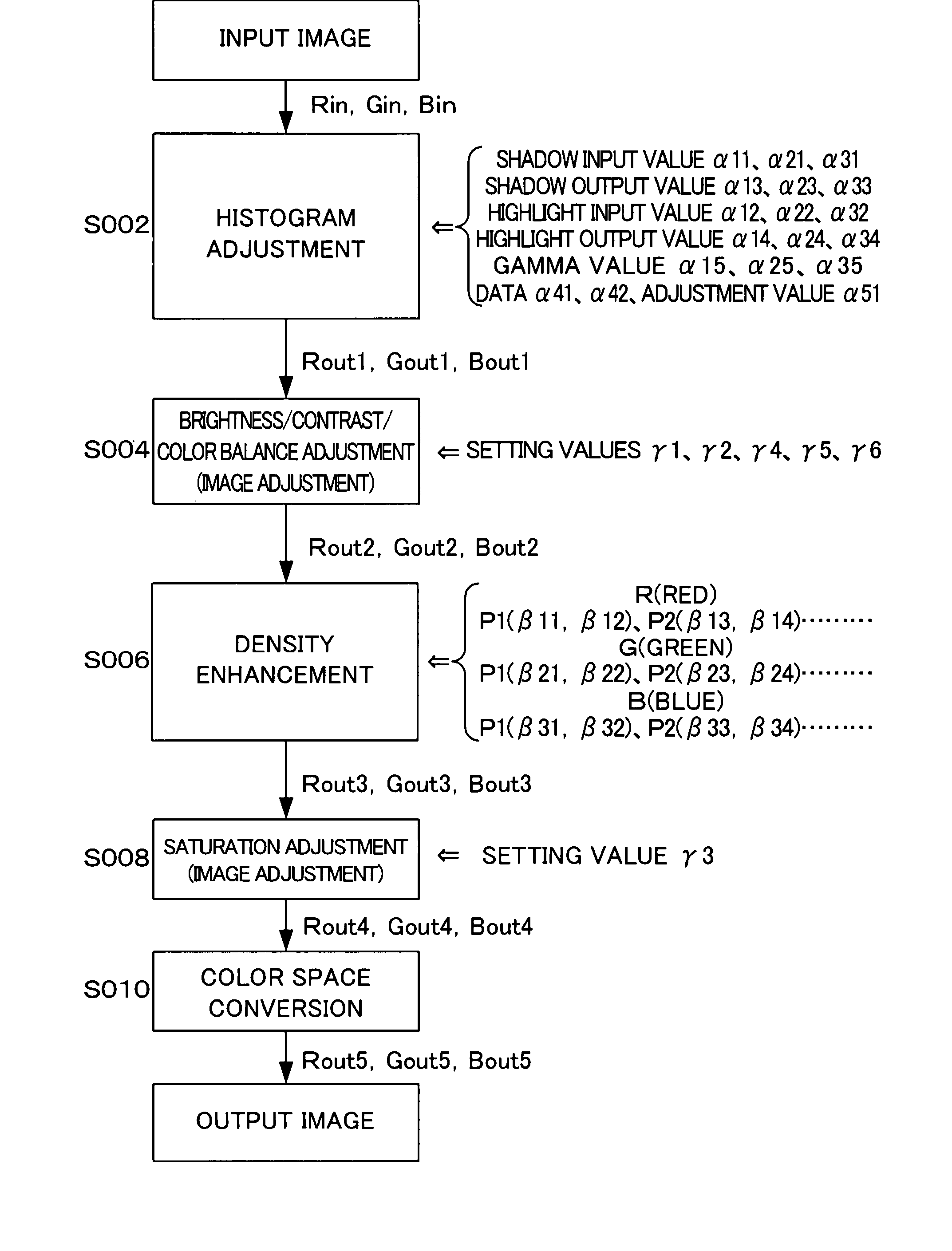
[0268] In the first embodiment, if the “backlight enhancement checkbox 130E” in the main dialog box 100 of the user interface illustrated in FIG. 5 has been checked by the user, then the scanner driver determines first whether the image read in with the image reading device 10 is a backlight image or not. It should be noted that here, the image to be determined that is subjected to the determination by the scanner driver is an image that has been adjusted (enhanced) automatically or by the user through the above-described histogram adjustment, density adjustment and image adjustment. Then, if the scanner driver has determined that the image read in with the image reading device 10 is a backlight image, this image is subjected to backlight enhancement. In the following, first a method for determining with the scanner driver whether the image read in with the image reading device 10 is a backlight image or not is explained. It should be no...

second embodiment

(2) Backlight Image Enhancement Process

[0347] In the second embodiment, if the “backlight enhancement checkbox 130E” in the main dialog box 100 of the user interface illustrated in FIG. 5 has been checked by the user, then the scanner driver performs a backlight enhancement process on the image read in with the image reading device 10. It should be noted that here, the image that the scanner driver subjects to a backlight enhancement process is an image that has been adjusted (enhanced) automatically or by the user through the above-described histogram adjustment, density adjustment or image adjustment. In the second embodiment, the scanner driver performs a backlight enhancement process on the image read in with the image reading device 10, regardless of whether the image read in with the image reading device 10 is a backlight image. The computer 20 executing the scanner driver that subjects the image read in with the image reading device 10 to a backlight enhancement process cor...

application examples

(2) Other Application Examples

[0441] In the above-explained determining method, regions given by histograms for the three colors red (R), green (G) and blue (B) were partitioned respectively into four small regions, namely the first to fourth small regions Ry1, Ry2, Ry3 and Ry4, but it is not necessarily required to partition them into four small regions Ry1, Ry2, Ry3 and Ry4. That is to say, it is sufficient if the regions given by the histograms for the three colors red (R), green (G) and blue (B) are partitioned into at least two small regions, and they may also be partitioned into three small regions or partitioned into five or more small regions.

[0442] Moreover, in the above-noted determining method, the four small regions Ry1, Ry2, Ry3 and Ry4 obtained by dividing the regions given by the histograms for the three colors red (R), green (G) and blue (B) included three small regions Ry1, Ry2 and Ry3 of substantially equal area and substantially equal pixel number, but it is not ...


PUM


Abstract

A backlight image determining apparatus includes: (A) a histogram data generation section that, based on data of pixels constituting an image to be determined, generates data of histograms for respective colors, the histograms representing a distribution of the number of pixels in respect to density values of the respective colors of those pixels; (B) an attribute information obtaining section that obtains, for each color, attribute information relating to a first small region and a second small region by partitioning regions given by the histograms for the respective colors into at least three small regions according to the magnitude of the density values, based on the data of the histograms for the respective colors generated by the histogram data generation section, selecting for each color at least one small region from the at least three small regions as the first small region, and selecting, from the at least three small regions, for each color at least one small region whose density values are larger than those of the first small region and which is not adjacent to the first small region, as the second small region; and (C) a determination section that determines whether the image to be determined is a backlight image, based on the attribute information relating to the first small region for each color and the attribute information relating to the second small region for each color, which is obtained with the attribute information obtaining section.

Description

CROSS-REFERENCE TO RELATED APPLICATIONS [0001] The present application claims priority upon Japanese Patent Application No. 2006-091366 filed on Mar. 29, 2006, and Japanese Patent Application No. 2006-128440 filed on May 2, 2006, which are herein incorporated by reference. FIELD OF THE INVENTION [0002] The present invention relates to backlight image determining apparatuses, backlight image determining methods, backlight image enhancement apparatuses and backlight image enhancement methods. DESCRIPTION OF THE RELATED ART [0003] Various image reading devices such as image scanners generally are connected to a so-called computer device such as a personal computer through a wired or a wireless connection and the like, and transmit an image that was read from an original document to the computer device as image data. The computer device receives the image data that have been transmitted from the image reading device and stores those data on a data memory device such as various memories ...

Claims


Application Information

Patent Timeline
Patent Type & Authority Applications(United States)
IPC IPC(8): G06K9/34
CPCH04N1/4074
Inventor OHARA, TAIRA
Owner SEIKO EPSON CORP
Why Eureka
Try Eureka