Apparatus and method for indicating locus of an ultrasonic probe, ultrasonic diagnostic apparatus and method
an ultrasonic probe and locus technology, applied in the field of apparatus and methods for indicating locus of ultrasonic probes, ultrasonic diagnostic apparatus and methods, can solve the problems of missed scans, difficult identifying scan planes by ultrasonic images, doctor cannot pay enough attention to the operation of ultrasonic probes, etc., to achieve the effect of improving accuracy and efficiency of examination
- Summary
- Abstract
- Description
- Claims
- Application Information
AI Technical Summary
Benefits of technology
Problems solved by technology
Method used
Image

Examples
first exemplary embodiment
(Components)
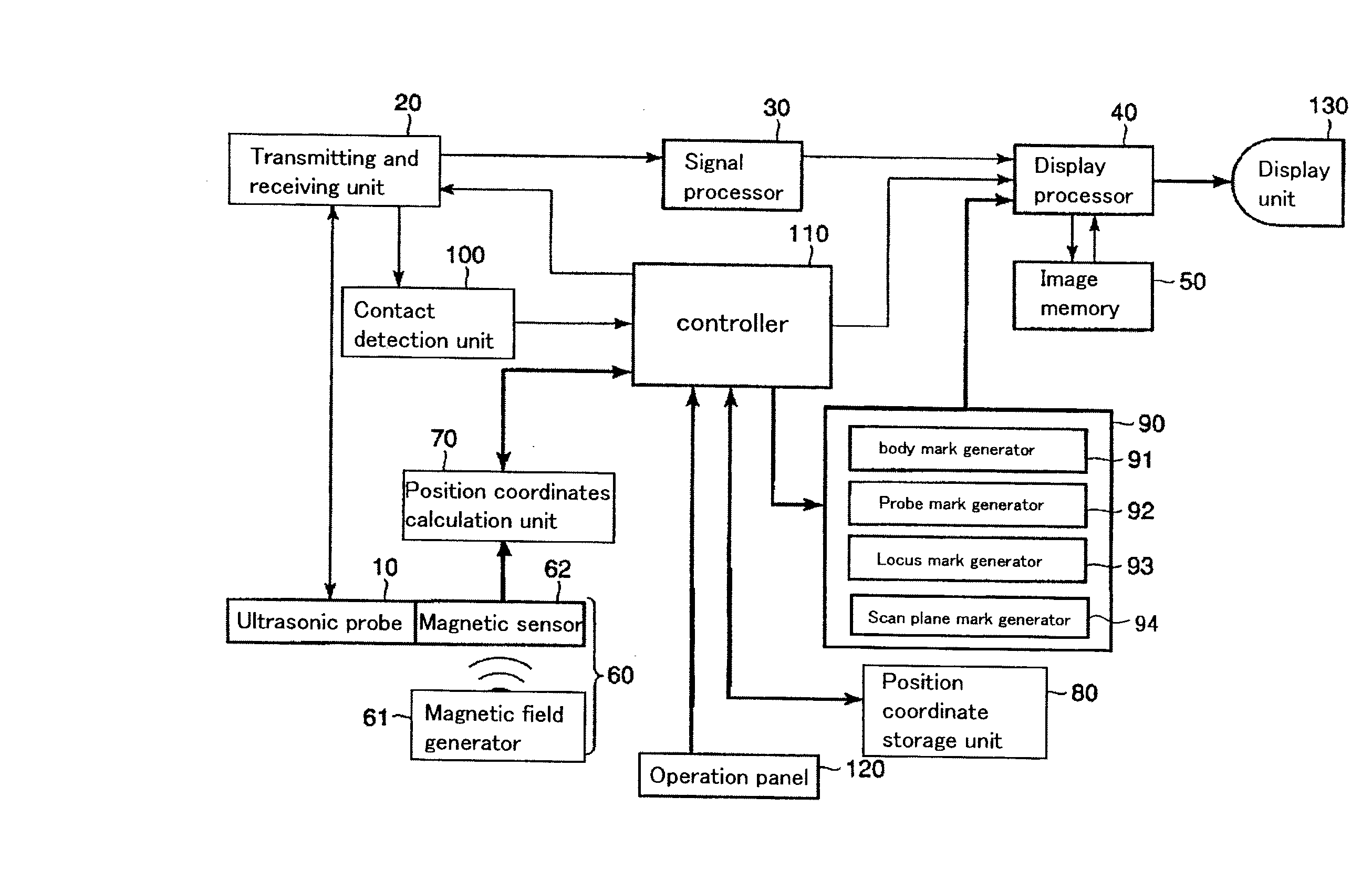
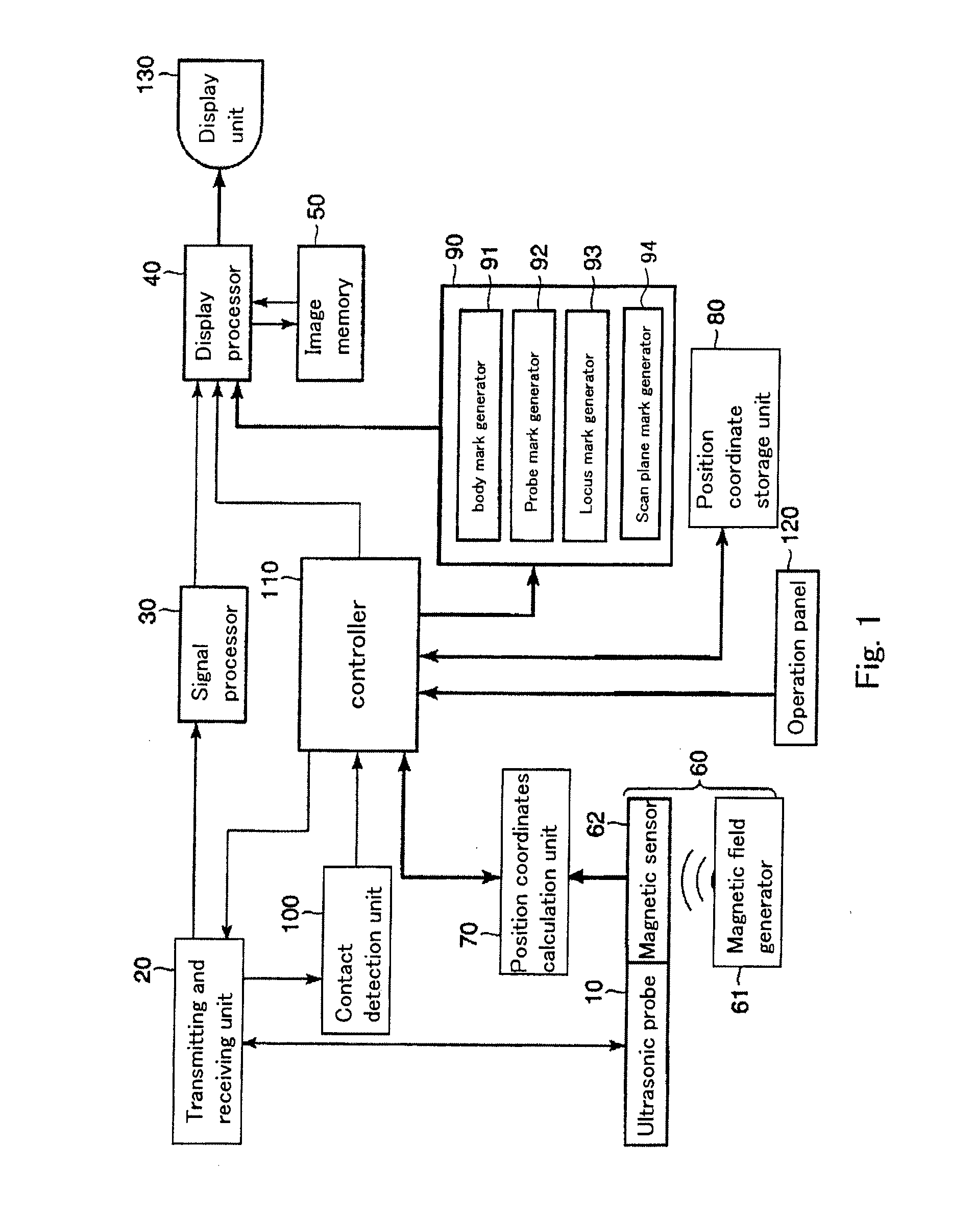
[0038] As shown in FIG. 1, an ultrasonic diagnostic apparatus of a first exemplary embodiment includes an ultrasonic probe 10, a transmitting and receiving unit 20, a signal processor 30, a display processor, a image memory 50, a position sensor 60, a position coordinates calculating unit 70, a position coordinates storage unit 80, a reference mark generator 90, a contact detection unit 100, a control unit 110, an operation panel 120 and a display unit 130.
[0039] The ultrasonic probe 10 transmits and receives ultrasonic to an examined part of a subject S. A piezoelectric vibrator is arranged in a casing of the ultrasonic probe 10. The piezoelectric vibrator is divided into a plurality of elements each constituting a part of a channel. If the ultrasonic probe 10 has a two dimensional arrayed vibrator, three-dimension data can be acquired.
[0040] The transmitting and receiving unit 20 includes a pulsar circuit, a delay circuit and a trigger generation circuit. The pulsa...
second exemplary embodiment
[0093] Next, a second exemplary embodiment is explained with reference to FIG. 15 and FIG. 16.
[0094] In the first exemplary embodiment, a three-dimensional positioning system is used as the position sensor 60 for detecting position coordinates of ultrasonic probe 10. However, in the second exemplary embodiment, as shown in FIG. 15, an image sensor, e.g., often used in an optical mouse, is used as a position sensor 60A.
[0095] The position sensor 60A is fixed at the ultrasonic probe and detects distance and direction of moving of the ultrasonic probe 10. Therefore, the position sensor 60A cannot detect absolute position coordinates of the ultrasonic probe 10 in the same way as the position sensor 60 in the first exemplary embodiment. However, the image sensor in the position sensor 60A is less expensive than the magnetic sensor 62. Furthermore, usage of the image sensor 60A is uninfluenced by a disturbance of magnetic field due to metals or such materials so use of the sensor 60A is...
third exemplary embodiment
[0098] Next, a third exemplary embodiment is explained with reference to FIG. 17.
[0099] In the second exemplary embodiment, the body mark BM is displayed in a two dimensional form. However, in this exemplary embodiment, a body mark BM and a locus mark LM are displayed in a three dimensional form.
[0100] At first, generation of the body mark BM will be explained. At a first step, position coordinates (X, Y, Z) of every part of P0-P4 of the breast B are obtained. These coordinates indicate three dimensional position information, so on the basis of this position information, a three dimensional form of the breast B is calculated. The probe mark generator 91 generates a body mark which indicates a three dimensional view of the breast B. One example of such a body mark of the breast B in perspective view is shown in FIG. 17(a). The body mark BM may be in wire frame form or in the form of a plurality of cubic blocks. In this exemplary embodiment, the probe mark BM is formed by a pluralit...
PUM
 Abstract
Description
Claims
Application Information
 - Generate Ideas
- Intellectual Property
- Life Sciences
- Materials
- Tech Scout
- Unparalleled Data Quality
- Higher Quality Content
- 60% Fewer Hallucinations
Browse by: Latest US Patents, China's latest patents, Technical Efficacy Thesaurus, Application Domain, Technology Topic, Popular Technical Reports.
© 2025 PatSnap. All rights reserved.Legal|Privacy policy|Modern Slavery Act Transparency Statement|Sitemap|About US| Contact US: help@patsnap.com