
Device and method of spacer and trial design during joint arthroplasty

a trial design and joint arthroplasty technology, applied in the field of joint replacement, can solve the problems of long recovery process, patient to consider and ultimately undergo joint replacement surgery, and possible complications

Inactive Publication Date: 2007-10-11
ORTHO SENSING TECH
View PDF13 Cites 161 Cited by
  • Summary
  • Abstract
  • Description
  • Claims
  • Application Information

AI Technical Summary

Benefits of technology

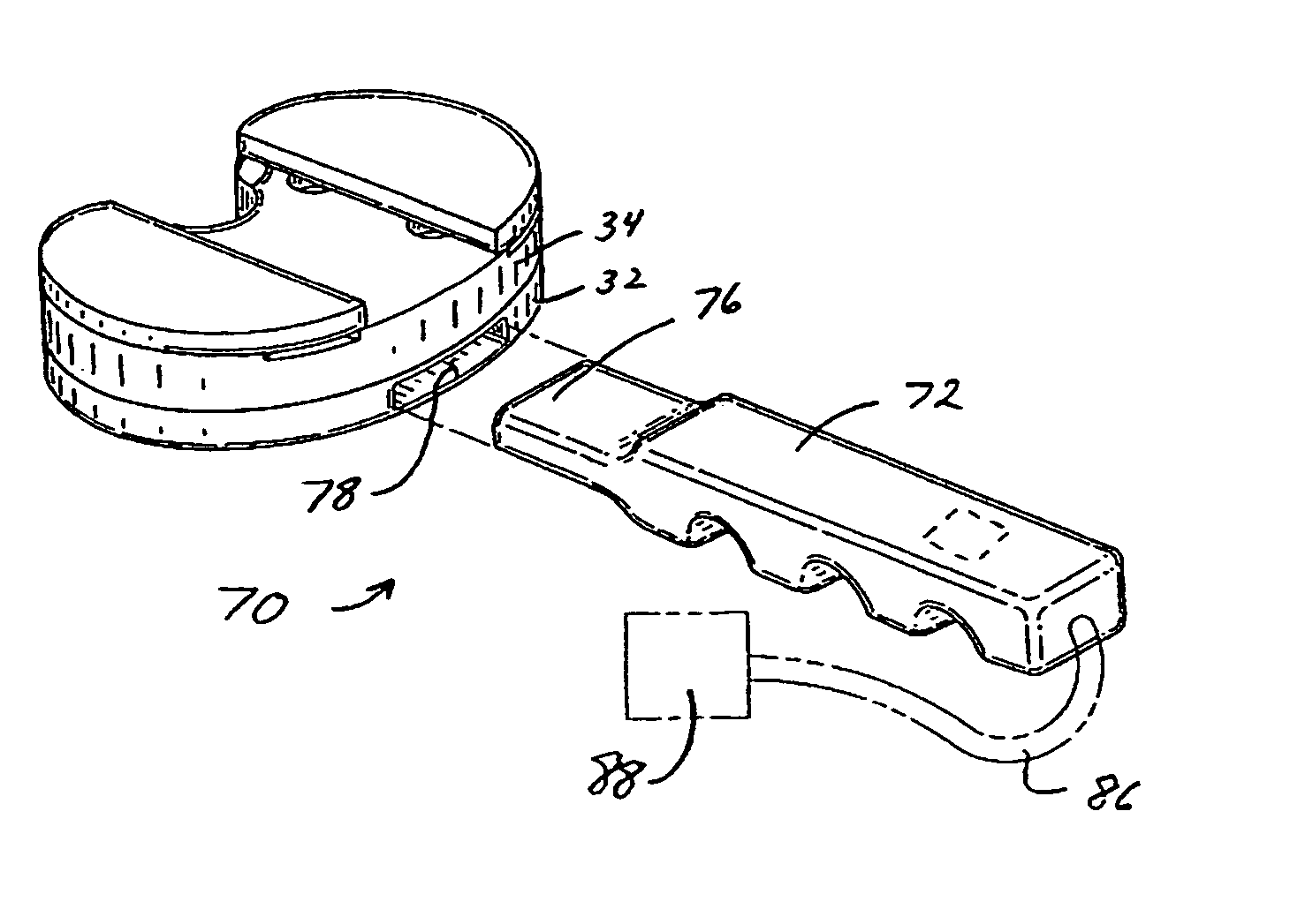
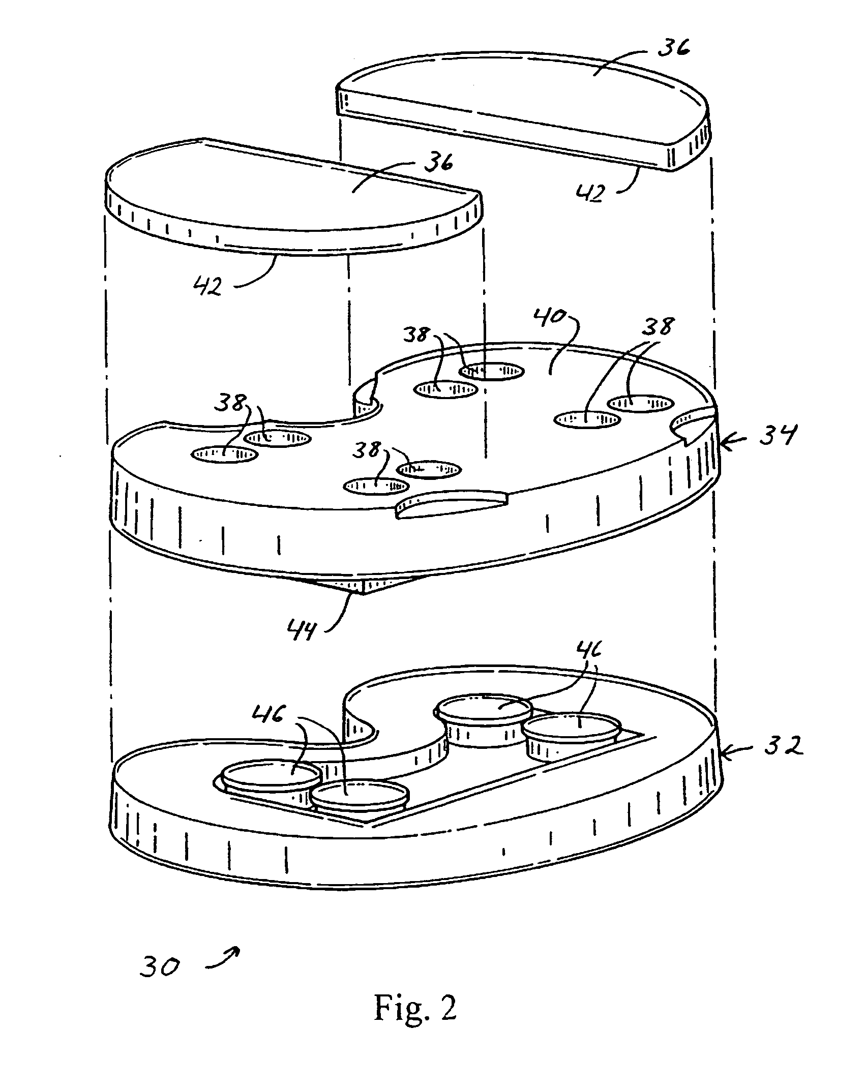
[0014] In overcoming the above limitations and other drawbacks, a spacer block is provided that includes a first body piece, a second body piece positioned on top of the first body piece. The first body piece includes at least one sensor that measures forces, such as dynamic contact forces, between the first and second body pieces. The spacer block includes a processor that includes a memory. The processor is operatively coupled to the sensor to receive data therefrom.

Problems solved by technology

Some medical conditions may result in the degeneration of a human joint, causing a patient to consider and ultimately undergo joint replacement surgery.
The long-term success of the surgery oftentimes relies upon the skill of the surgeon and may involve a long, difficult recovery process.
As with all major surgical procedures, complications may occur.
While temporary components such as spacers and trials serve important purposes in gathering information prior to implantation of a permanent component, one drawback associated with temporary components is that a physician may need to “try out” different spacer or trial sizes and configurations for the purpose of finding the right size and thickness, and for balancing collateral ligaments and determining an appropriate permanent prosthetic fit, which will balance the soft tissues within the body.
However, when relying on feedback from a sedated patient, the feedback may not be accurate since it is subjectively obtained under relatively poor conditions.
Thus, after surgery, relatively fast degeneration of the permanent component may result.
One limitation associated with available systems that use of sensors is that, while objective feedback is obtained, that feedback is limited to the number of sensors that are employed and the number of physical tests that are performed.

Method used


Image

  • Device and method of spacer and trial design during joint arthroplasty
  • Device and method of spacer and trial design during joint arthroplasty
  • Device and method of spacer and trial design during joint arthroplasty

Examples


Embodiment Construction

[0037] The present invention is directed to a spacer block for use in prosthesis fitting and balancing in joints. It will be apparent that the device described herein below, may be applied to a variety of medical procedures, including, but not limited to, joint replacement surgeries performed on the shoulder, elbow, ankle, foot, fingers and spine.

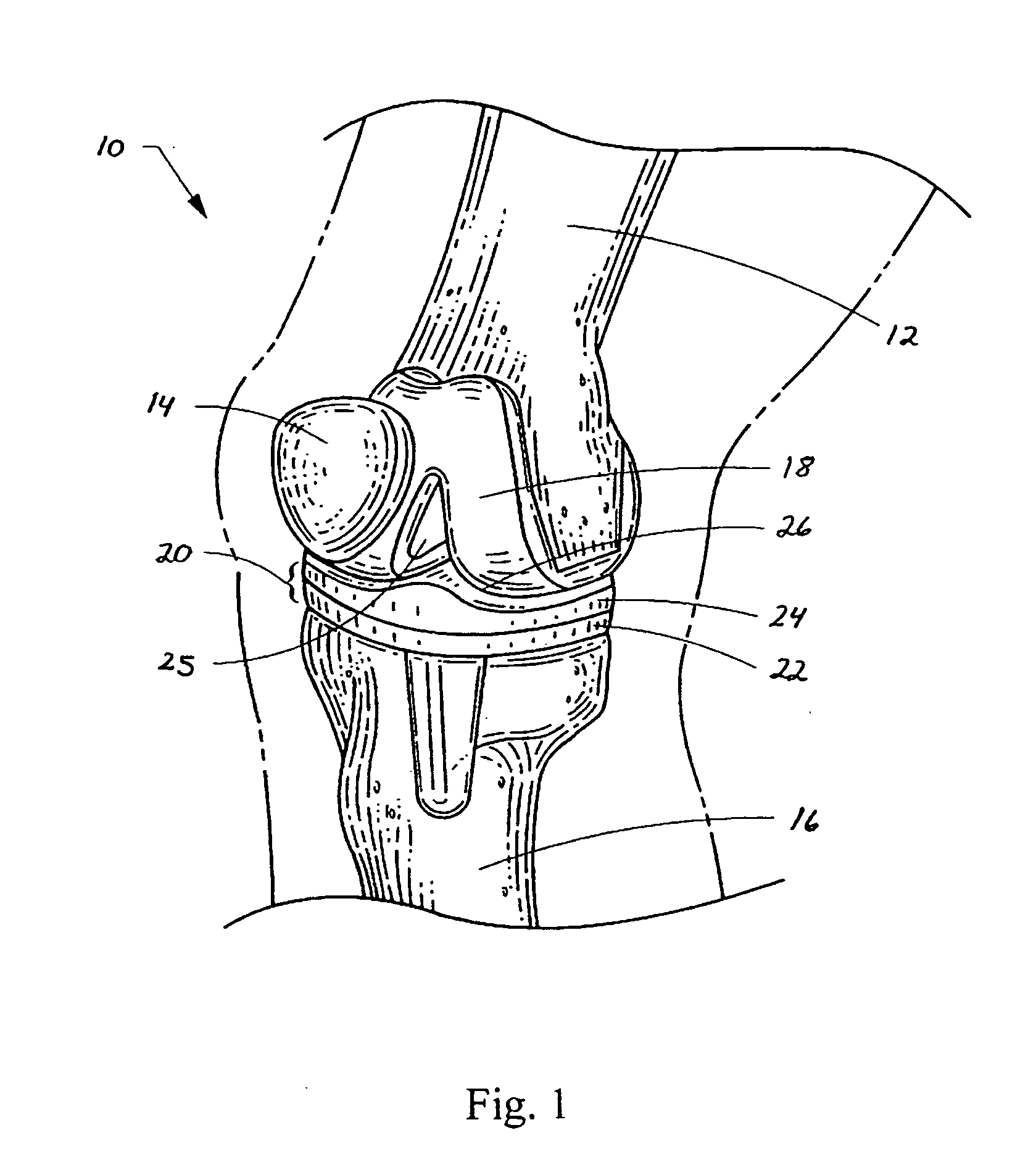
[0038] Referring now to FIG. 1, a schematic of a human knee undergoing a total knee arthroplasty (TKA) procedure is shown. In general, the human knee 10 comprises a femur 12, a patella 14, a tibia 16, a plurality of ligaments (not shown), and a plurality of muscles (not shown). An exemplary prosthesis that may be used during a TKA procedure comprises a femoral component 18 and a tibial component 20. The tibial component 20 may comprise a tibial tray 22 and a trial insert 24. The trial insert 24 may be temporarily attached to the tibial tray 22, or alternatively, may be integrally formed to provide a trial bearing surface. Trial inserts 24 ...


PUM


Abstract

A spacer block for gathering data to be used in selection of a trial insert includes a first body piece, a second body piece positioned on top of the first body piece, and at least one chim positioned on top of the second body piece. The first body piece includes at least one sensor to measure forces between the first and second body pieces, and the spacer block includes a processor having a memory operatively coupled to the sensor. The data can be analyzed using a trained neural network to provide feedback to a physician to aid in the determination of whether to resect additional bone, release soft tissues, and / or select sizes for a trial insert. Advantageously, increased data may be provided to a physician without the need to acquire numerous samples from a patient, and fewer sensors may be employed.

Description

BACKGROUND [0001] 1. Technical Field [0002] The invention relates to joint replacement, and more particularly, to a spacer block used to provide data to assist in selecting the size of a trial implant. [0003] 2. Related Applications [0004] This application incorporates by reference applicant's co-pending applications U.S. patent application Ser. No. ______ (Attorney Docket No. 12462 / 4), filed concurrently herewith and entitled “Application of Neural Networks to Prosthesis Fitting and Balancing in Joints,” and U.S. patent application Ser. No. ______ (Attorney Docket No. 12462 / 6), filed concurrently herewith and entitled “Force Monitoring System.”[0005] 3. Related Art [0006] Some medical conditions may result in the degeneration of a human joint, causing a patient to consider and ultimately undergo joint replacement surgery. The long-term success of the surgery oftentimes relies upon the skill of the surgeon and may involve a long, difficult recovery process. [0007] The materials used...

Claims


Application Information

Patent Timeline
Patent Type & Authority Applications(United States)
IPC IPC(8): A61F5/00A61F2/30A61B5/103
CPCA61B5/1121A61B5/4528A61B5/4585A61B2562/0247A61B2562/0252A61B2562/0261A61B5/7267A61F2/38A61F2/4657A61F2/4684A61F2002/4633A61F2002/4666A61B2562/046
Inventor AMIROUCHE, FARID
Owner ORTHO SENSING TECH
Learn More