

Automated tightening shoe
- Summary
- Abstract
- Description
- Claims
- Application Information
AI Technical Summary
Benefits of technology
Problems solved by technology
Method used
Image

Examples
first embodiment
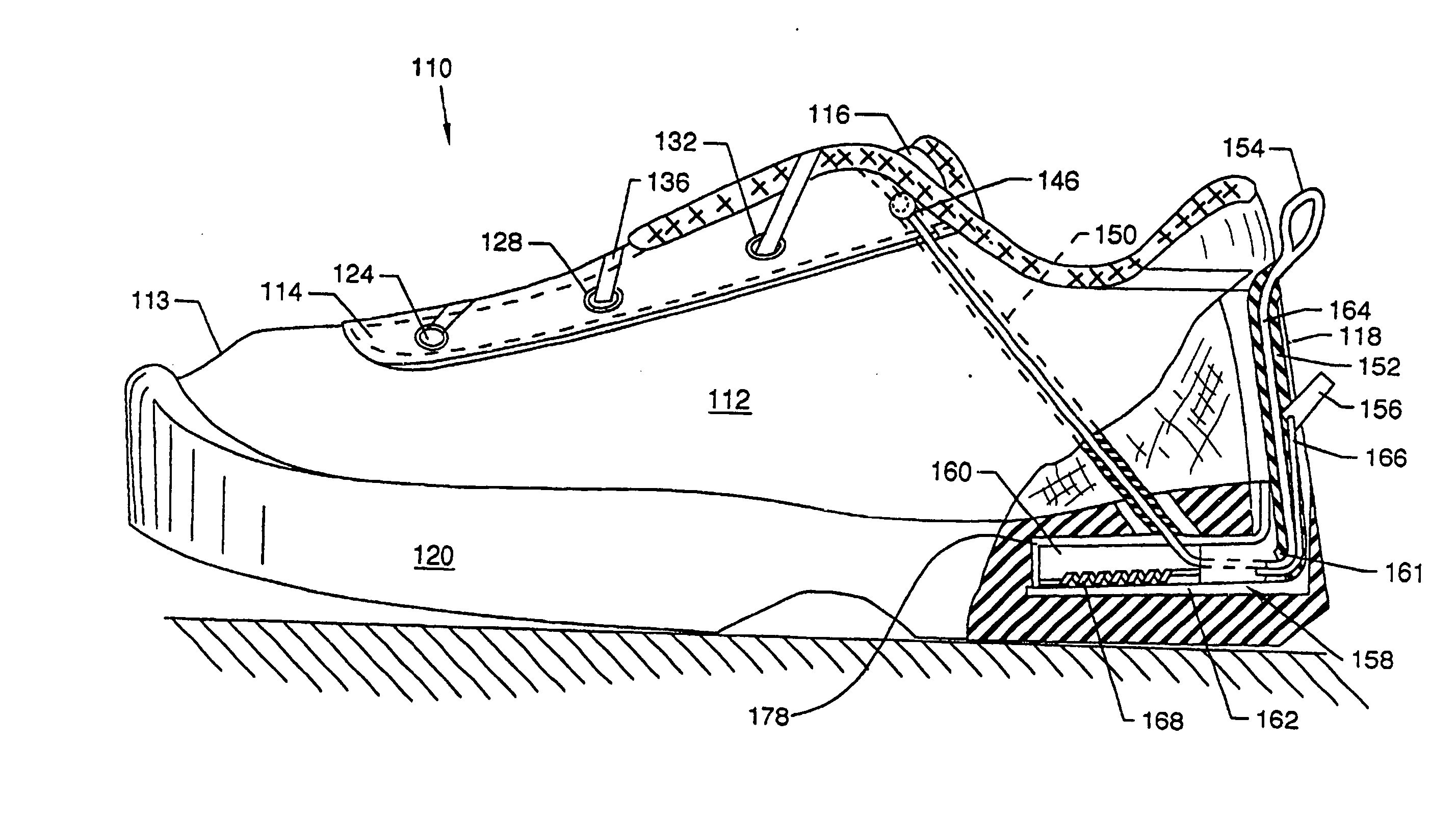
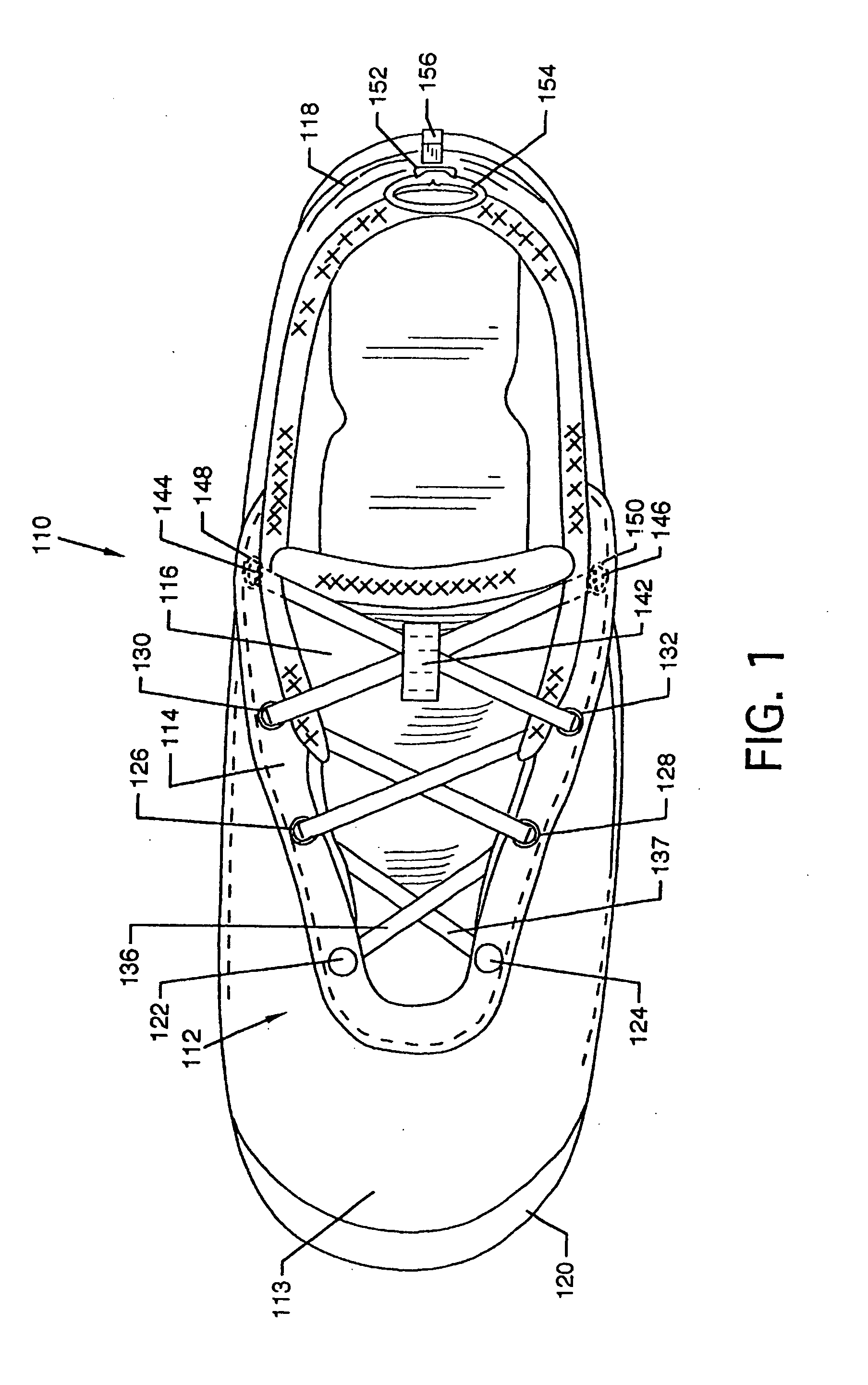
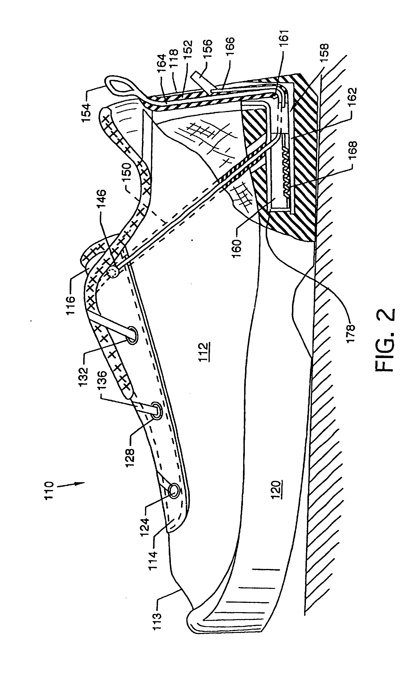
[0042]FIG. 1 illustrates a top view of an automated tightening shoe 110 of the present invention in the open condition, and FIG. 2 illustrates a side view, in partial cutaway, of the automated tightening shoe 110 with the tightening mechanism. The automated tightening shoe 110 has a sole 120, an integral body member or shoe upper 112 including a tongue 116, a toe 113, a heel 118, and a reinforced lacing pad 114, all constructed of any appropriate material for the end use application of the shoe.
[0043] At the toe 113 end of tongue 116, there are provided two anchor buttons 122 and 124 which are secured to shoe laces 136 and 137, respectively, at one end. The shoe laces 136 and 137 then crisscross over tongue 116 and pass through lace eyelets 126, 128, 130, and 132, as illustrated, before passing through lace containment loop 142. After passing through lace containment loop 142, lace 136 passes through a hole 146 in the reinforced lacing pad 114 and travels downwardly and rearwardly t...
third embodiment
[0049]FIG. 7 depicts a rear view of the automated tightening shoe 110, incorporating a track and slide mechanism 288, which constitutes the tightening mechanism of the present invention, where all numerals which have appeared previously correspond to those elements previously described. With additional reference to FIG. 5, the track and slide mechanism 288 can be substituted for the pulling loop 154 and release lever 156. The track and slide mechanism incorporates a track 290, which is frictionally engaged by a slide 292 that travels vertically along the length of track 290. By moving the slide 292 upwardly along track 290, the engagement lace 164 is actuated, thereby causing the automated tightening shoe 110 to tighten. Conversely, by moving the slide 292 downwardly along track 290, the engagement lace 164 is released, thereby enabling the automated tightening shoe 110 to be loosened.
fourth embodiment
[0050]FIG. 8 illustrates a bottom view of the automated tightening shoe 110 with the sole 120 and mechanism base 162 removed for purposes of illustrative clarity to reveal tightening mechanism 358, and FIG. 9 illustrates a partial cross sectional view the tightening mechanism 358, where all numerals which have appeared previously correspond to those elements previously described. This tightening mechanism 358 can be substituted for the tightening mechanisms 158, 258 and 288 previously described for the invention without affecting the function or scope thereof. Tightening mechanism358 is comprised of a housing plate 178 to which is secured a pair of axle support members 372 and 374, which extend downwardly in a perpendicular fashion and accommodate a ratchet wheel axle 370. A ratchet wheel 364 containing ratchet teeth 366 along its perimeter is secured along ratchet wheel axle 370 midway between axle support members 372 and 374. A release lever 360 is pivotally secured to housing pla...
PUM
 Abstract
Description
Claims
Application Information