Contained load transfer device for wood sheathing products and roof construction method therewith

a load transfer device and load transfer technology, which is applied in the direction of roofs, walls, constructions, etc., can solve the problems of difficult application of adhesive tape, certain reduction of potential adhesion, and high undesirable effects of such a purpose, and achieve the effect of convenient and safe installation, reliable attachment of such devices, and convenient and safe manner

Inactive Publication Date: 2007-10-18
HUBER ENGINEERED WOODS
View PDF10 Cites 17 Cited by
  • Summary
  • Abstract
  • Description
  • Claims
  • Application Information

AI Technical Summary

Benefits of technology

[0005] It is an advantage of the present invention to provide a simple manner of reliably connecting building roof component wood boards together during roof construction therewith. Another advantage of such a device and method is the ability of a user to easily install such devices within target wood boards and further connect an adjacent wood board thereto through the utilization of at least one such device in order to keep such wood boards in place for a sufficient period of time prior to attachment to a roof frame.
[0006] The invention herein may be summarized as a structure for an edifice selected from the group consisting of a roof and a wall, wherein said structure is comprised of at least a first wood board and a second wood board, each of said first and second wood boards having a top portion and a bottom portion, and each having four peripheral edges, wherein at least one peripheral edge of each wood board includes at least one cavity therein for the insertion of at least one connection device; wherein said connection device is made of a durable material and having a first end and a second end and wherein each of said first and second end is configured to be inserted within said at least one cavity of each wood board; wherein when said first and second wood boards are contacted simultaneously with said device, said peripheral edges into which said device is inserted are parallel to each other, but are not in contact with one another, and wherein said device does not contact the top or bottom portion of said first and second wood boards. Furthermore, the roof or wall structure as defined above may include limitations such as: wherein said first end and said second end are shaped exactly the same and of the same dimensions, wherein said device is configured in such a manner that either of said first or second end may be placed within said at least one cavity within said peripheral edge of said first wood board, said cavity exhibiting a shape and dimension that is complementary to said first or second end of said device, and wherein when present within said cavity of said first wood board, said second wood board may then be contacted with said second end of said device in relation to the same type of cavity as defined for said first wood board within said peripheral edge of said second wood board. A method of manufacturing a roof in accordance with such a scheme and utilizing at least two such wood boards for such a purpose is encompassed within this invention as well.
[0007] Such a device should therefore preferably be symmetrical in shape and measurements in order to exhibit the necessary ability to be inserted within cavities of any wood board used therewith. The size of such a device may be of any width, up to the length of the peripheral edge of the target wood board(s) less an inch and a half (i.e., about 3.8 centimeters), generally. As the length of typical spacing between roof joists for roof construction wood boards are about 24 inches on center (i.e., about 61 centimeters), such a device may thus be as wide as 22.5 inches (roughly about 57 centimeters). At its smallest, such a device would be about 1 inch (2.54 centimeters) wide. Preferably, though not necessarily, a multiple amount of such devices would be utilized to connect adjacent boards together during the construction of a roof or wall, mainly because of the facilitation of maneuverability a user would have with smaller devices in hand during roof construction, rather than large materials for such a purpose.
[0008] As such, the device may be incorporated within a roll containing a release liner with an adhesive attaching such multiples of devices to thereto from which they may be peeled and applied within the cavities of wood boards, potentially with the adhesive transferred therewith to permit reliable attachment of such devices to target wood boards. In this manner, a user would have a relatively convenient and safe manner of not only transporting such multiple devices, but also applying an adhesive-including device to a target wood board.
[0009] The utilization of an adhesive is also preferable if the device(s) are transported by a user by different means. As such, an adhesive may be applied by the user by hand prior to utilization, or such devices may have covering strips over an already-applied adhesive area thereon, from which the strip may be removed by the user prior to utilization and insertion within a wood board cavity. Any other manner of adhesive application may also be followed for such a purpose.
[0010] The device itself may be constructed of any durable material, and of any shape and dimension, as long as the overall appearance is, as noted above, symmetrical. Thus, plastics (including high density plastics like polyurethane, polyethylene, polypropylene, polyethylene terephthalate, polyacrylate, polyacetyl, and the like), metals (including iron, steel, aluminum, and the like), and any type of hardwood (oak, cedar, and the like), may be utilized to such an end. Combinations of such materials (such as mixtures of different plastics, a plastic coated metal or wood, and the like), may also be utilized.

Problems solved by technology

Such clips, known in the industry as H-clips, exhibit disadvantages, however, that render them highly undesirable for such a purpose.
For instance, such H-clips make it difficult to apply adhesive tape (for, among other purposes, sealing seams to prevent water penetration therein and air leaks) along the spaces between boards conjoined by such clips, particularly since such clips are applied to the exterior of such boards.
The adhesive tape applied to such boards must thus be in contact with such clips as well as such boards, thereby exhibiting a certain reduction in potential adherence thereto and compromising the effectiveness of such tape (or like adhesive material).
Also, it has been problematic to apply certain load forces to roof structures including such H-clips, particularly during manufacturing steps thereof, as such clips exhibit a propensity for disengaging upon application of excessive weight on certain portions of component boards.
To date, the wood board roofing component industry has not been accorded such an improvement.

Method used


Image

  • Contained load transfer device for wood sheathing products and roof construction method therewith
  • Contained load transfer device for wood sheathing products and roof construction method therewith
  • Contained load transfer device for wood sheathing products and roof construction method therewith

Examples


Embodiment Construction

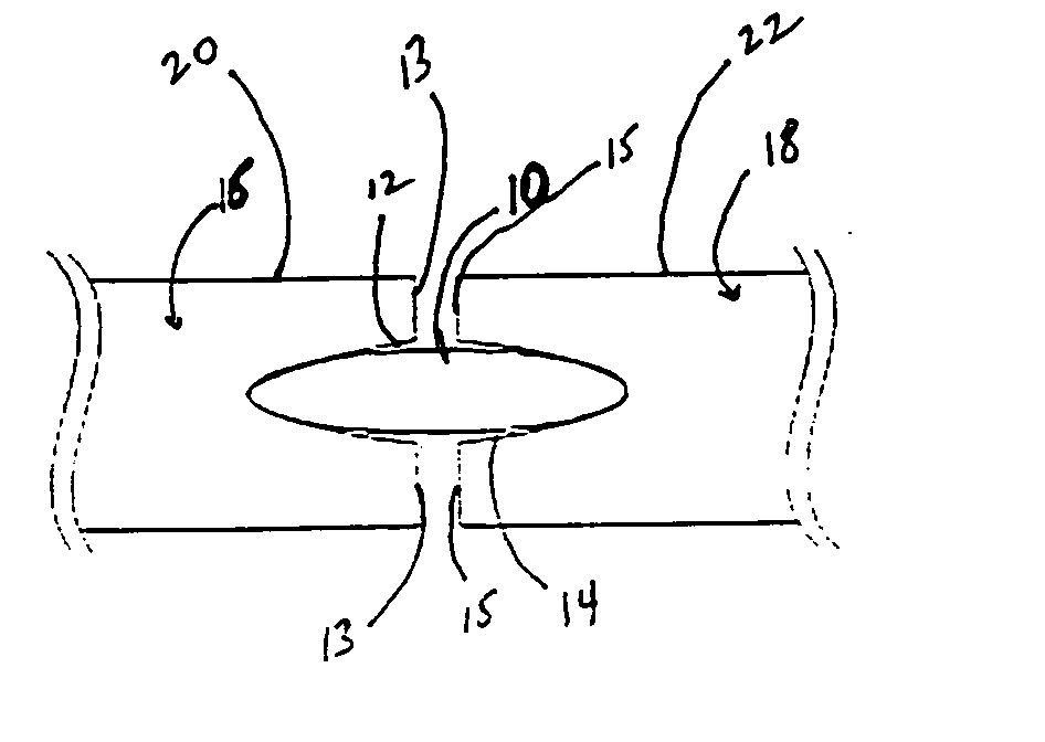
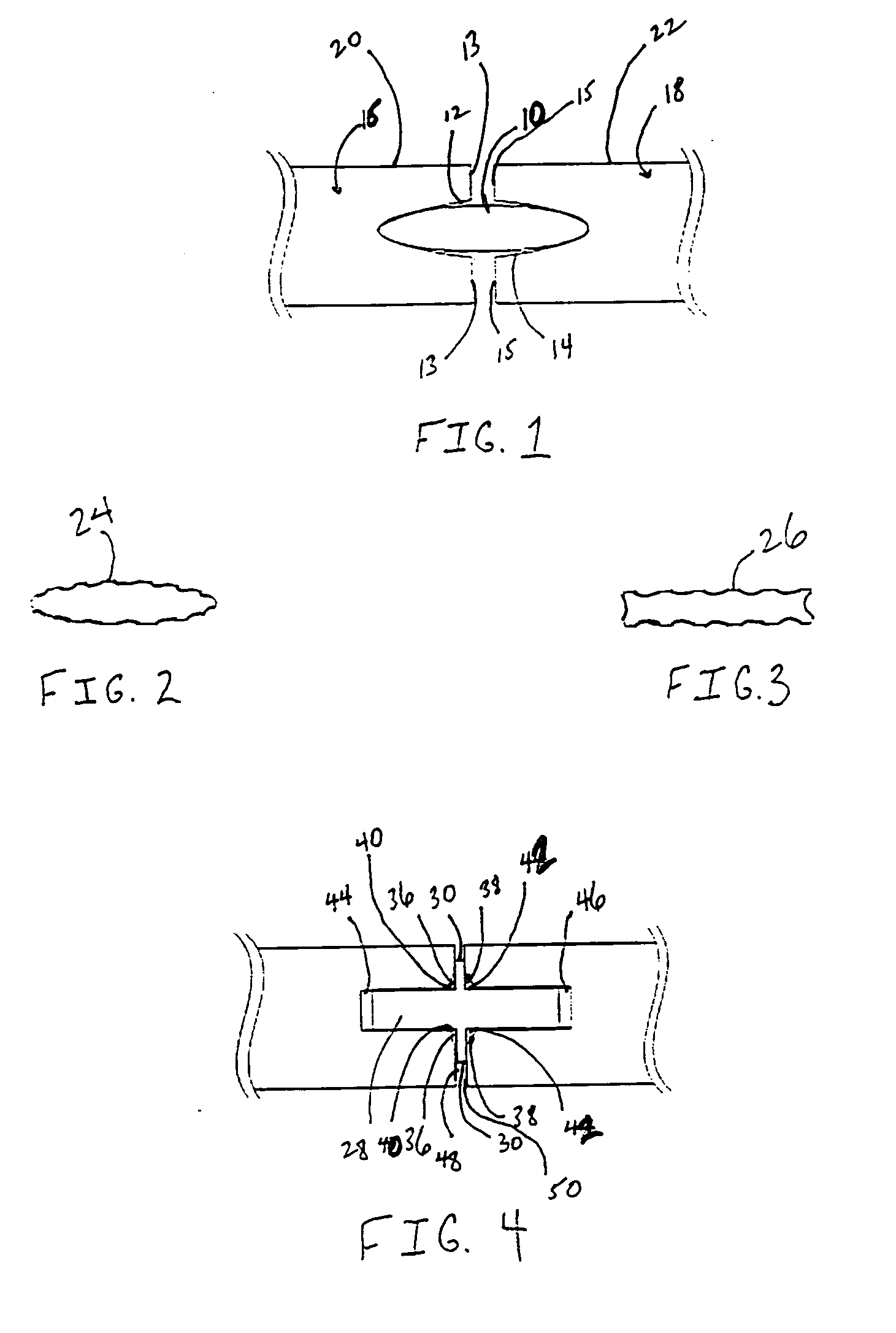
[0022]FIG. 1 shows a cross-sectional perspective of a disk 10 inserted within the cavities 12, 14 of peripheral edges 13, 15 of two adjacent wood boards 16, 18. As can be seen, the disk 10 is flush with the internal portions of said cavities 12, 14 to the degree that a distance between both boards 16, 18 is evident. A tape (not illustrated) may then be applied in contact with the top portions 20, 22 of both wood boards 16, 18. When multiple disks are utilized, the distance between the wood boards 16, 18, will be roughly uniform along the peripheral edges 13, 15.

[0023] The disks of FIGS. 2 and 3 merely show that such devices, either oval in shape 24, or rectangular in shape 26, may be modified or produced originally in such a manner as to impart an increase in surface area thereto to aid in adhering such devices to the cavities in which they are inserted within wood boards (not illustrated).

[0024]FIG. 4 depicts a cross-sectional perspective of a different potential embodiment where...


PUM


Abstract

The utilization of a specific load transfer device for the purpose of allowing for reliable connection and adhesion of composite wood boards during edifice manufacture therewith is provided. Such a device is configured for containment within slots cut into the peripheral edges of such wood boards and cut into a shape therein that is complementary to that of the device itself. In such a manner, the device, when introduced within the properly shaped slot, permits separation of adjacent wood boards that are sequentially applied to the frame of the target edifice, as well as, ultimately, sufficient load bearing strength for the overall construction (such as a roof) within which such connected wood boards are utilized. The separation of wood boards thus permits proper sealing therebetween (with tape, sealant, or other like material) as well as proper distance for shrinking or swelling (due to moisture / temperature variations) to be taken into account during the lifetime of the edification (thereby permitting expansion as needed). The ability to impart increased load bearing strength thus allows for an increase in construction materials (in number and in weight) to be carried and kept on such a structure during construction as well. The method of manufacture of an edifice utilizing such load transfer devices between wood boards is also encompassed within this invention.

Description

FIELD OF THE INVENTION [0001] The subject invention relates to the utilization of a specific load transfer device for the purpose of allowing for reliable connection and adhesion of composite wood boards during edifice manufacture therewith. Such a device is configured for containment within slots cut into the peripheral edges of such wood boards and cut into a shape therein that is complementary to that of the device itself. In such a manner, the device, when introduced within the properly shaped slot, permits separation of adjacent wood boards that are sequentially applied to the frame of the target edifice, as well as, ultimately, sufficient load bearing strength for the overall construction (such as a roof) within which such connected wood boards are utilized. The separation of wood boards thus permits proper sealing therebetween (with tape, sealant, or other like material) as well as proper distance for shrinking or swelling (due to moisture variations) to be taken into account...

Claims


Application Information

Patent Timeline
Patent Type & Authority Applications(United States)
IPC IPC(8): E04B2/00
CPCE04B1/6145E04F2201/0505E04D3/18E04B1/68E04D3/36E04B1/541
Inventor BENNETT, JOHN LANDUSTHOMAS, VINCENT B.JORDAN, RICHARD D.
Owner HUBER ENGINEERED WOODS
Why Eureka
Try Eureka