Piston, method of producing the piston, and pump having the piston

a technology of piston and piston plate, which is applied in the direction of positive displacement liquid engines, machines/engines, flexible member pumps, etc., can solve the problems of reducing the unable to ensure durability which is practically sufficient, and difficulty in smooth rolling of the cylindrical outer peripheral portion, etc., to shorten the time of washing the pump pressure chamber, improve the durability, and improve the constant flow rate and liquid displacement performance of the pump

Active Publication Date: 2007-10-18
TORAY ENG CO LTD +1
View PDF7 Cites 21 Cited by
  • Summary
  • Abstract
  • Description
  • Claims
  • Application Information

AI Technical Summary

Benefits of technology

[0010]The invention has been conducted in view of the problems. It is an object of the invention to provide a piston which can be used in a pump for supplying a corrosive liquid, which can improve the durability, and

Problems solved by technology

In the conventional piston made of a fluororesin, unlike a piston made of rubber, the cylindrical outer peripheral portion of the piston does not have a sufficient flexibility, and hence it is difficult to cause the cylindrical outer peripheral portion to smoothly roll without producing deflections or bends in the gap between the outer face of the piston support member and the inner face of the cylinder, while being in close

Method used


Image

  • Piston, method of producing the piston, and pump having the piston
  • Piston, method of producing the piston, and pump having the piston
  • Piston, method of producing the piston, and pump having the piston

Examples


first embodiment

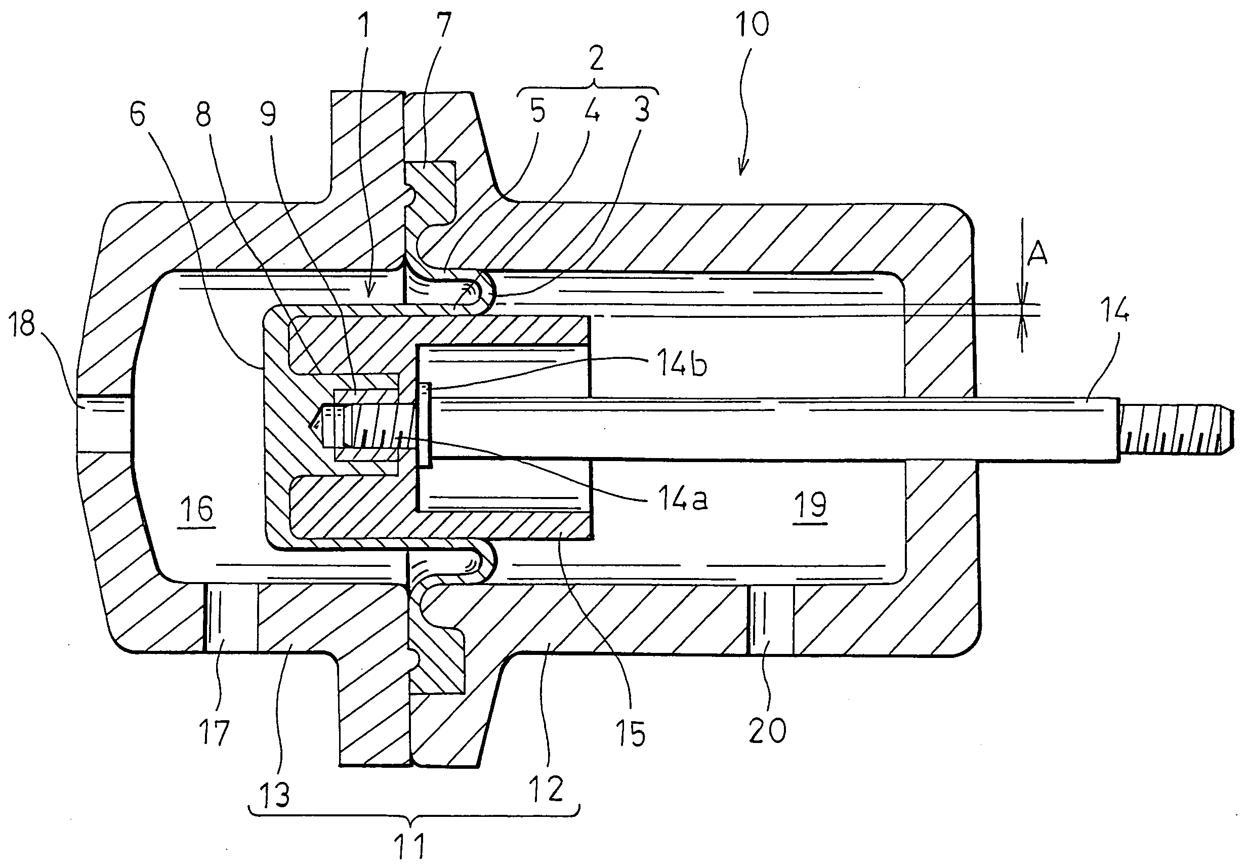
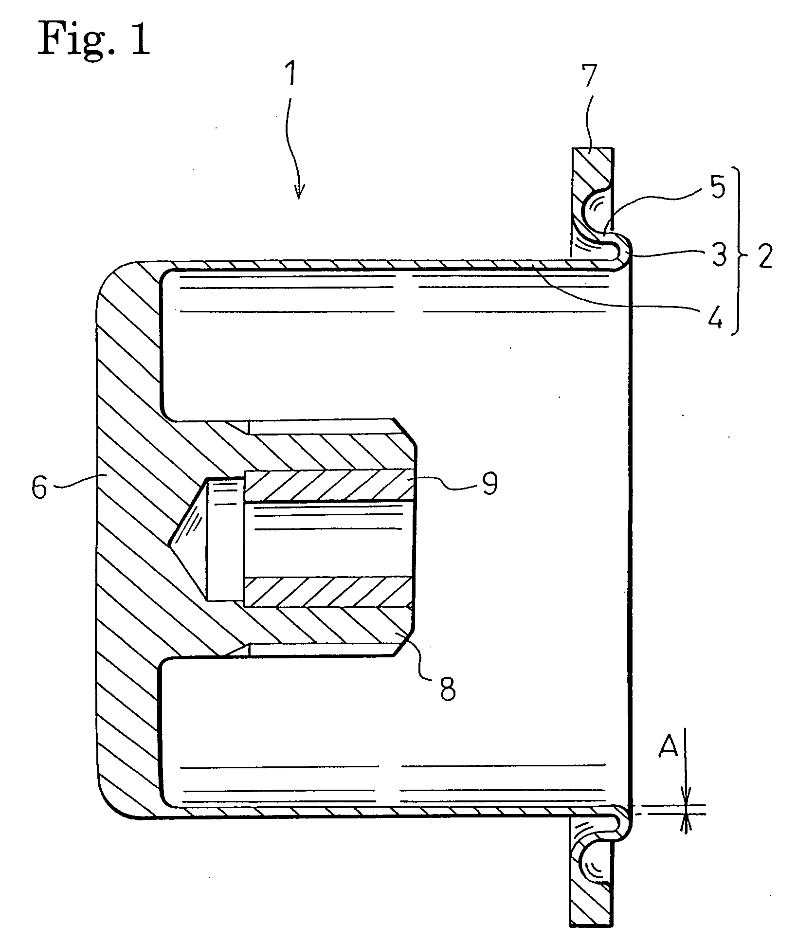
[0033]FIG. 1 is a section view showing a piston of a The piston 1 is formed by a fluororesin such as PTFE (polytetrafluoroethylen), and comprises a cylindrical outer peripheral portion (hereinafter, referred to as “rolling portion”) 2 which is formed by folding back (winding back) an intermediate portion to the inner side or the outer side. The rolling portion 2 is configured by: a folded-back portion 3 having a bending angle of about 180 degrees; and inner and outer peripheral portions 4, 5 which extend in the same direction from the inner and outer peripheral ends of the folded-back portion 3 in parallel with the axial line, respectively. In an end portion of the inner peripheral portion 4, a disk-like end plate portion 6 which forms the end portion into a closed end portion is disposed. In an end portion of the outer peripheral portion 5, a flange portion 7 which is an annular plate member perpendicularly rising from the end portions toward the radially outward side is disposed....

second embodiment

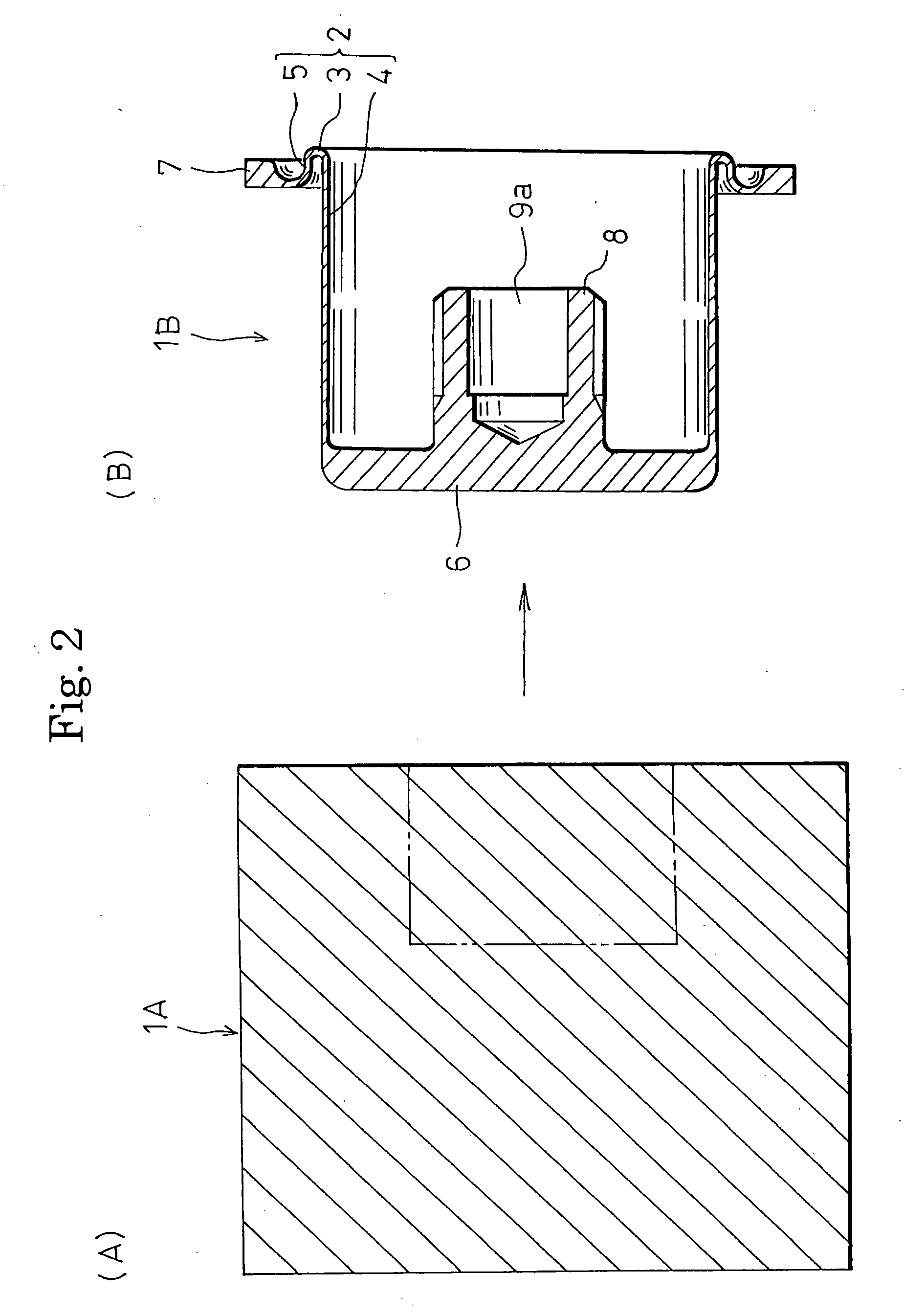
[0047]FIG. 5 is a view illustrating a method of producing the piston of the When the piston 21 is to be produced, a workpiece 21A which is shown in (A) of FIG. 5, and which is made of a fluororesin such as PTFE is prepared. In the illustrated example, the workpiece 21A has a columnar external shape which is slightly larger than the piston 21. Alternatively, the workpiece may have a polygonal columnar shape. In order to reduce the material cost, a recess may be formed in a middle portion of one end face as indicated by the phantom line.

[0048]The piston 21 is produced in the following manner. The workpiece 21A is cut to be formed into the piston body 21B of the piston 21 into which the metal sleeve 9 has not yet been fixed, as shown in (B) of FIG. 5. In the piston body 21B, in addition to the rolling portion 2 (the folded-back portion 3, the inner peripheral portion 4, and the outer peripheral portion 5), the end plate portion 6, the flange portion 7, and the protrusion 8, a bottomed...

fifth embodiment

[0067]In the method of producing the piston of the fourth or fifth embodiment, as apparent from the production method, in the case where the piston semifinished product 41B or 51B in a state where the folded-back portion 3 of the piston 41 or 51 is bent back is to be molded, when the band-back angle is within a range from about 90 degree to about 180 degree, the piston body 41C or 51C of the piston 41 or 51 can be properly formed by the secondary process even when the piston semifinished product has been bent back at any angle.

[0068]FIG. 16 is a section view of a pump comprising the piston of the fourth or fifth embodiment. The pump 42 (the pump comprising the piston of the fourth embodiment), or the pump 52 (the pump comprising the piston of the fifth embodiment) is used for supplying quantitatively and at a constant flow rate a chemical solution such as a resist solution that is to be used in a process for producing an FPD such as an LCD, or a semiconductor device. The piston 41 o...


PUM

PropertyMeasurementUnit
Lengthaaaaaaaaaa
Thicknessaaaaaaaaaa
Fractionaaaaaaaaaa

Abstract

A piston 1 which is to be movably supported in a cylinder 11 of a pump 10 to be reciprocally driven is formed by a fluororesin so that it is not impaired by a corrosive liquid. A cylindrical outer peripheral portion 2 of the piston 1 has a thickness of 1 mm or less, and is flexible. The outer peripheral portion has a flange portion 7 in an open end portion via an approximately 180-degree folded-back portion 3. The flange portion 7 is attached to the cylinder 11. When the pump 10 is driven, the cylindrical outer peripheral portion 2 of the piston 1 smoothly rolls without producing deflections or bends in a gap between the outer peripheral face of a piston support member 15 and the inner peripheral face of the cylinder 11, while being in close contact with the two faces.

Description

BACKGROUND OF THE INVENTION[0001]1. Field of the Invention[0002]The present invention relates to a piston, a method of producing the piston, and a pump having the piston.[0003]2. Description of the Prior Art[0004]Among pumps, a pump is conventionally known in which a diaphragm formed by rubber is used as a piston that is movably supported in a cylinder to be reciprocally driven. In the diaphragm serving as a piston, a closed end portion of the diaphragm is attached to a piston support member which is movably supported in the cylinder to be reciprocally driven while disposing a gap between the member and the inner face of the cylinder, and a cylindrical outer peripheral portion of the diaphragm is attached to the cylinder by a flange portion which is provided in an open end portion of the outer peripheral portion via an approximately 180-degree folded-back portion. In a pump comprising such a piston, suction and discharge ports for a liquid are opened in a pressure chamber which is d...

Claims


Application Information

Patent Timeline
IPC IPC(8): F01B19/00
CPCF04B43/0054F04B43/02Y10T29/49261F16J3/06F05C2225/04F16J1/00F16J1/01
Inventor UEHARA, JUNICHITESHIMA, KAZUKIYO
Owner TORAY ENG CO LTD
Why Eureka
Try Eureka