Fluid flow indicator

a flow indicator and flow tube technology, applied in the direction of instruments, hose connections, apparatus for dispensing discrete objects, etc., can solve the problems of patient breathing difficulty, similar breathing difficulty, and inability to fully expand the lungs, so as to facilitate the flow of fluid, prevent damage to the valve member, and minimize the possibility of kinking

Inactive Publication Date: 2007-10-18
AVONMED HEALTHCARE
View PDF42 Cites 23 Cited by
  • Summary
  • Abstract
  • Description
  • Claims
  • Application Information

AI Technical Summary

Benefits of technology

[0008] Because the protrusions deform upon engagement with the tubular element, this arrangement results in an enhanced sealing effect between the protrusions and the tubular element.
[0044] In one case the receptacle is configured to be carried by a patient. Preferably the device comprises a carrier member, configured to be worn by a patient, for carrying the receptacle. The receptacle may be attached to the carrier member by any suitable means, such as a clip, and / or a belt attachment, and / or a hook-and pile fastener. The carrier member may be provided in any suitable form, such as a strap to be worn over one shoulder and across the torso of the patient. In another case the device comprises a support member for supporting the receptacle. Preferably the support member comprises a support arm movable between a storage configuration and a supporting configuration. Ideally the receptacle is configured to hang from the carrier member and / or from the support member. Most preferably the receptacle is configured to hang substantially upright. By hanging the receptacle upright, this arrangement minimizes the possibility of accidental spillage from the receptacle. By always maintaining the collection vessel receptacle vertically upright using the pivot connection arrangement of the belt attachment to the collection vessel receptacle, this ensures that the collection vessel receptacle volume may be easily read using the graduations. Preferably the receptacle comprises a vacuum port. Ideally the device comprises a valve at the vacuum port. The receptacle may comprise a solidifier to solidify a body fluid drained into the receptacle. At least part of the outer surface of the receptacle may be substantially concave in shape. The concave outer surface of the receptacle may conform to the outer surface of a patient to enable the receptacle to be carried / worn in a compact, low-profile manner.

Problems solved by technology

When air enters or becomes trapped inside the pleural cavity, the lungs cannot fully expand, and the patient experiences difficulty breathing.
Often there is a combination of both air and blood present in the pleural cavity, causing similar difficulties breathing.

Method used


Image

  • Fluid flow indicator
  • Fluid flow indicator
  • Fluid flow indicator

Examples


Embodiment Construction

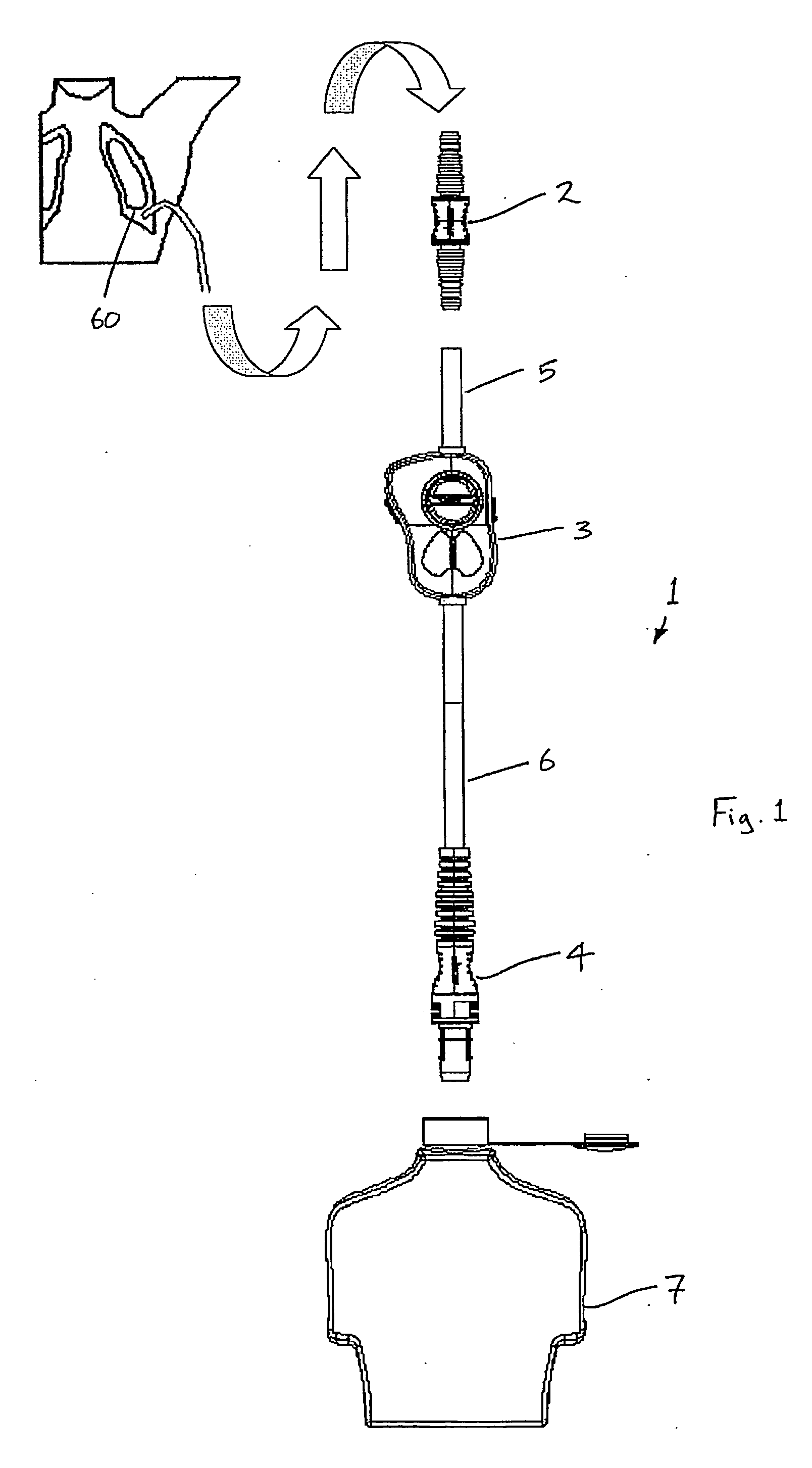
[0088] Referring to the drawings, and initially to FIGS. 1 to 15 thereof, there is illustrated a medical drainage device 1 according to the invention. The device 1 is particularly suitable for draining fluid from a pleural cavity 60 of a patient. The fluid may be drained from the pleural cavity 60 by relying on gravitational force only or alternatively suction may be applied to assist in drainage of the fluid.

[0089] In this patent specification, the term fluid will be understood to mean a gas, such as air, or a liquid, such as blood, or a combination of a gas and a liquid.

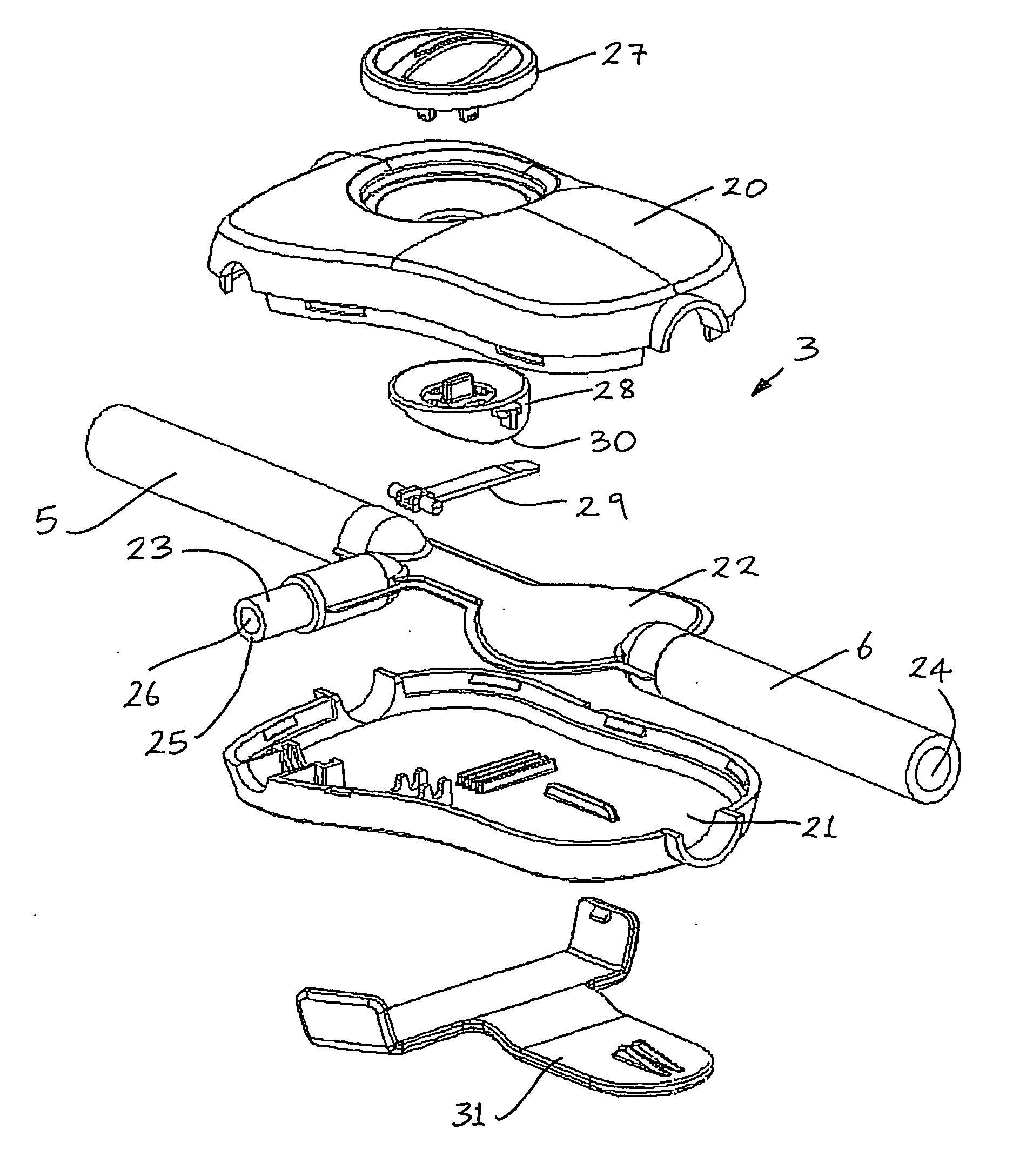
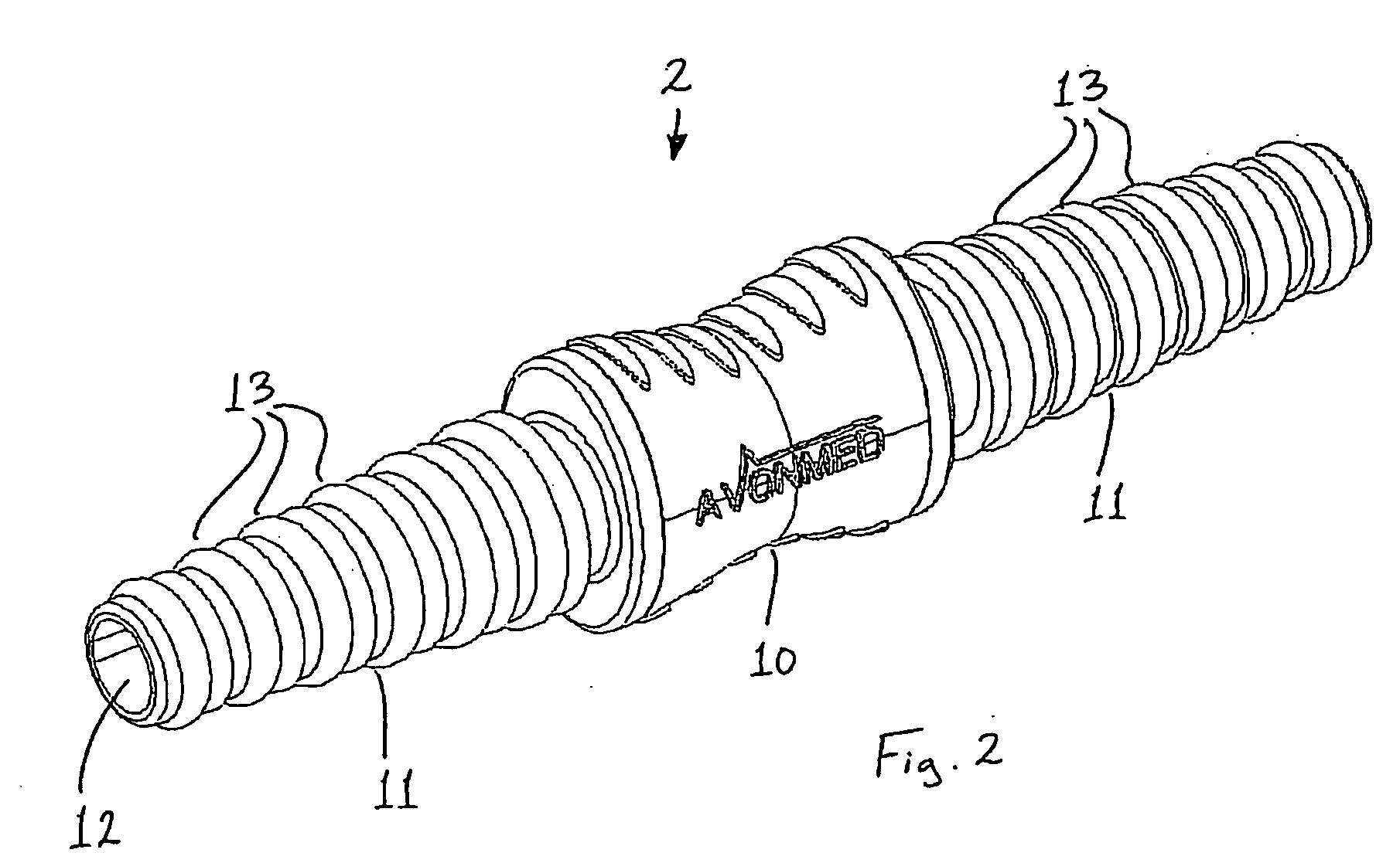
[0090] The device 1 comprises a barb connector 2, a fluid flow indicator 3, a chest drainage unit (CDU) connector 4, a tubular upper drain tube 5 between the barb connector 2 and the fluid flow indicator 3, a tubular lower drain tube 6 between the fluid flow indicator 3 and the CDU connector 4, and a receptacle 7.

[0091] The barb connector 2 is suitable for being connected to the upper drain tube 5.

[0092] As ill...


PUM

PropertyMeasurementUnit
volumeaaaaaaaaaa
volumeaaaaaaaaaa
volumeaaaaaaaaaa

Abstract

A fluid flow indicator (3) for use in a medical drainage device for draining fluid from a pleural cavity of a patient comprises an upper housing part (20), a lower housing part (21), a balloon member (22), a sampling port (23), and a control mechanism to selectively control flow of a body fluid through the balloon member (22) or through the sampling port (23). The balloon member (22) defines a lumen therethrough. Upon flow of a body fluid into the balloon member (22), for example upon inhalation of a patient, the balloon member (22) inflates from a deflated rest configuration to an inflated flow configuration. This inflation of the balloon member (22) provides a visual indication to an operator of the flow of the body fluid through the balloon member (22). When flow of the body fluid ceases, for example upon exhalation of a patient, the balloon member (22) deflates from the inflated flow configuration to the deflated rest configuration. This deflation of the balloon member (22) provides a visual indication to the operator of the cessation of the flow of the body fluid through the balloon member 22).

Description

INTRODUCTION [0001] This invention relates to a device suitable for connection to a substantially tubular element, to a fluid flow indicator, and to a medical drainage device. [0002] In the human anatomy, between the outer surface of the lungs and the chest wall lies an area known as the pleural cavity. Under normal conditions in a healthy patient, the pleural cavity is a closed space and is at negative pressure or vacuum so that the lungs fully expand during the respiration inhalation. When the chest wall is opened, for example as a result of surgery or chest injury, the in-rush of air causes the vacuum in the patient's pleural cavity to be lost and atmospheric air to enter the pleural cavity. Since the normal vacuum is no longer present, the lungs collapse as they depend upon this vacuum to stay fully expanded up against the chest wall. When air enters or becomes trapped inside the pleural cavity, the lungs cannot fully expand, and the patient experiences difficulty breathing. Thi...

Claims


Application Information

Patent Timeline
Patent Type & Authority Applications(United States)
IPC IPC(8): G07F11/00G08B21/00
CPCA61M5/16886A61M39/02A61M39/223A61M39/285A61M2039/1077A61M2039/1088A61M1/0086A61M2210/101B29C45/14598B29C2045/14459B29K2083/00B29L2031/753F16L33/227A61M2205/583A61M1/86
Inventor DURKIN, ANTHONYREGAN, DESMOND JOHN
Owner AVONMED HEALTHCARE
Why Eureka
Try Eureka